
 |
|
Three different optics exist for the H10. They differ mainly in the magnification factor between the primary target (T4 or T8) and the NA50 target:
     RUN <227>TREE        for P41 mode
     RUN <245>TREE        for P61 mode
Normally the beam X-terminal is configured such that the correct tree is
started automatically.
Detailed indications can be found in the P41/P42 handbook, copies of which are available in the CRN as well as in the NA50 control room.
Note :The commands in the tree should all be upper case
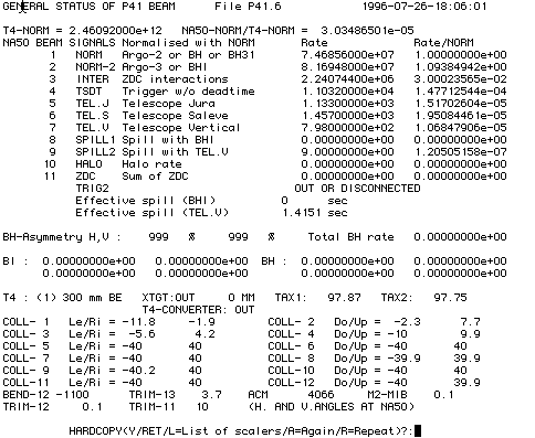
The general performance is easily monitored through the command
STATUS / GENERAL
This shows the intensities in 12 NA50 counters, as well as the most relevant settings related to the behaviour of the beam. Compare with previous settings in the logbooks in the CRN or at the exepriment. An example is shown below:

The size of the beam spot and the impact point can be measured in an analog wire chamber located slightly more than a metre upstream of the NA50 target. The profiles can be visualised by typing
TUNE / MEAS/ MWPC / PROFILEand replaying DICO to show the profile in a graphics window on your X-terminal. Please see below for indications on how to correct the steering of the beam, depending on the H10 optics in use.
Note : all currents are for 450 GeV/c
	Horizontal position		BEND-12			 6.0 Amps/mm
	Vertical position		TRIM-13			12.5 Amps/mm

	Horizontal angle		TRIM-12
	Vertical angle			TRIM-11
 	Horizontal position		B12 + 1.06 TR12		  45 Amps/mm
	Vertical position		TR13 + 4.75 TR11	0.84 Amps/mm
but the lever arm in horizontal position is only ~ 3 mm.
 	Horizontal position		B12 + 3.7 TR12		 24Amps/mm
	Vertical position		TR13+2.12 TR11		10.5 Amps/mm
but the lever arm in horizontal position is only ~ 3 mm.
The required currents can be activated by the commands
TUNE / SET / BEND / number / currentor
TUNE / SET / TRIM / number / current
The trajectories of particles implied by these settings are shown below:
The steering of the
P41 and
P61
beams is described in separate documents.
Last updated : 26 July 1996 by Lau Gatignon