M. Bourgeois, O. Camut, S. Chomenko, S. Kondrashev,
H. Kugler,
Yu. Satov, R. Scrivens, J. Tambini
The CO2 Master Oscillator (MO) for the CERN Laser Ion Source (LIS), should be delivered during 1997. It aims to provide a ~100 ns, 150 mJ single frequency, single transverse mode 10.6 mm output pulse. This low power, smooth laser pulse can then be amplified to produce the high intensity beam (>1012 W/cm2) required for the high charge-state ion production.
In an intermediate step, the Lumonics 601-TEA laser will be converted to a power amplifier, by removing the present resonator mirrors and installing a multi-pass system.
During November 1996 Yuri Satov and Sergej Chomenko of TRINITI, Troitsk and Sergej Kondrashev of ITEP, Moscow, visited CERN in order to deliver parts of the MO system, and measure the small signal gain coefficient (g) of the Lumonics.
The small signal gain coefficient of an active medium
(such as the discharge gas in the Lumonics laser) characterizes
the gain per unit length, at a level well below saturation. If
a beam of intensity I0 enters the medium and
is amplified in a length l, the small signal gain is given
by:-
where I is the output light intensity.
Detailed in this note are the results of the measurements
of g at different gas mixtures and at different positions
through the Lumonics. Finally the first estimates of the amplifier
scheme and the output energy will be presented.
The apparatus used for the measurements consisted
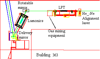
of 3 main parts. The scheme is shown in Figure 1.

Figure 1. Scheme of the LPT and Lumonics equipment, as set-up in building 363.
Low Pressure Tube (LPT) Laser
The LPT provided the initial laser light pulse for amplification by the Lumonics. It is based on the concept for the LPT in the final MO system, using a CO2:He:N2 low pressure (~5-6 mbar) gas mixture pumped by a subnormal (glow) longitudinal discharge. The resonator, with a length of 1.3m, is formed with one concave (R=8m) copper mirror and a Ge plate (60% reflection index for one face and AR-coated for second one). The absence of dispersion elements inside the resonator ensures the LPT-lasing on the P(20) line of the 10m-band (strongest line for future MO/Lumonics optical scheme). The output beam in general has one longitudinal mode (due to the narrow gain profile of the low pressure-broadening in the gas), providing a power of ~1 W for 0.5 ms (at 1 Hz rep. rate). The beam is polarized due to 2 Brewster plates providing the windows for the LPT.
The gas mixture was taken from the Lumonics supply
line. The LPT gas pressure was maintained using a flow rate controller
valve.
Lumonics Amplifier
The resonator mirrors of the Lumonics laser were removed, with a NaCl window providing the rear gas seal. Apart from this no further changes were made to the laser.
The beam from the LPT passed through the Lumonics
cavity and then via the 5 mirror chain to the target area in building
236.
Detection
The 10.6 mm
light from the LPT-Lumonics arrangement was focused using a 1 m
focal length aluminized glass mirror and detected using a liquid
Nitrogen cooled Ge-Hg-Au crystal, which has a higher sensitivity
than the normal photon drag detector.

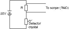
Figure 2. Electric scheme of the Cold IR detector.
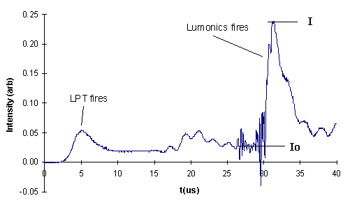
The amplified light duration was approximately 5 ms, much shorter than the duration of the LPT pulse. Therefore the intensities could be measured from the background level and peak height.
The electrical scheme of the detector is shown in
Figure 2. Using a R=1 kW
resistor (to produce a large signal) and a 4 m long coaxial
cable, gives a limit on the rise time of ~0.5 ms.
This was sufficient for these measurements.
A typical signal measured from the detector is shown in Figure 3.
Measurements were made of g with three different
gas mixtures in the Lumonics. The gas mixture is quoted in two
manners. The first is the direct ratio of the gases, and the second
is as measured on the flow tubes on the laser control unit. The
small signal gains at the different mixtures are shown in Table 1.

Figure 3. Typical trace from the IR detector, showing LPT intensity and Lumonics amplified signal. (Signal is inverted for clarity.)
| Gas mix (CO2:N2:He) | Flow Tube (He/CO2/N2) | g (%/cm) |
The small signal gain coefficient was measured at
different positions through the Lumonics cavity, to find an average
value, and to assess the effect of the variation in amplification
on the final beam profile. The results for 6 different positions
are shown in Figure 4.

Figure
4. Small signal gain coefficient (g) measured
at different horizontal positions between the anode and cathode
(squares) and at one different vertical position (circle).
The indicated error bars are for the 95% confidence
limits on the mean value, based on 9 - 14 shots at each
position. The cathode side showed a more unstable beam, possibly
due to the acoustic waves caused by the discharge, which normally
do not affect the Lumonics as a generator as the pulse is of the
order of 100 ns for the first spike.
Taking an average value for the small signal gain
coefficient of 3.7 %/cm gives leads to an estimation of a 3 pass
scheme for the Lumonics Power Amplifier. The estimation formula
for the beam energy gain for one pass of the amplifier is given
by:-
where Eout, Ein and Es
are the output energy density (J/cm2), the input energy
density and the saturation energy (a value applicable only to
this formula and listed in literature). The energy after each
pass is then E1=0.583 J, E2=4.2 J
and E3=20.6 J (for Ein=150mJ and Es=300 mJ/cm2)
[1-4]. Taking 80% of the final energy as useful energy gives Euseful=16.5 J.
The small signal gain coefficient of the Lumonics
601-TEA Laser, used by the CERN Laser Ion Source, has been measured
at a range of different gas mixtures and positions through the
gas chamber. The average value is g=3.7 %/cm, which with
preliminary calculations leads to a 3 pass scheme of the Lumonics
amplifier, delivering 16.5 J of useful energy. More accurate
simulations will be performed at TRINITI in order to see the time
behavior of the pulse.