
The plasma produced when a powerful laser pulse is focused onto
a target surface in vacuum can provide a copious source of highly
charged ions. Ions can then be extracted from the plasma to form
a high current, short pulse length ion beam. Experimental laser
ion sources have been the subject of investigation in medical
physics and particle accelerator applications; a laser ion source
is an option for the injection system of heavy ions for the Large
Hadron Collider at CERN where a high intensity lead ion beam is
required. This paper describes work carried out at CERN to develop
a CO2 laser ion source.
When a powerful laser pulse is focused onto a solid surface,
the solid absorbs laser radiation, leading to localised heating
and subsequent evaporation. Electrons in the cloud of vaporised
material absorb laser radiation by inverse Bremsstrahlung and
cause stepwise ionisation of metal atoms to form a plasma. After
a short time of some nanoseconds, the plasma reaches a critical
density whereupon absorption of laser radiation and thus plasma
electron temperature increase dramatically, and the plasma becomes
highly reflective to incoming laser light. The very hot dense
plasma formed by this process undergoes a rapid expansion normal
to the target surface, and a range of kinetic energy is imparted
to the ions1.
The maximum ion charge state produced by this process is determined
by the electron temperature of the plasma, since this sets the
maximum ionisation energy achievable by plasma electrons. The
controlling factor on the electron temperature is the power density
of the laser focused onto the target surface. Figure 1 (a) shows
the peak charge state produced from a lead target as a function
of CO2 laser power density2. The plasma
electron temperature is typically a few hundreds of electron volts
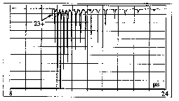
in this regime. The distribution of charge states within the
plasma can be measured using an energy selective electrostatic
analyser to separate individual charge states in time, as illustrated
in Figure 1 (b) for a tantalum target. This shows the maximum
charge state produced is 23+, with the peak of the distribution
at 20+. In a laser ion source the neutral plasma is allowed to
drift a certain distance in a field-free region, before the ions
are separated from the electrons and accelerated to form a beam
by a negative voltage applied to an extraction system. Note that
all charge states from the maximum down to 1+ are extracted, and
ions within the beam possess an energy spread characteristic of
the plasma in addition to the extraction energy.
of CO2 laser power density. ions produced
in CO2 laser plasma.
2.1 Target Chamber and beam extraction system
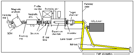
A schematic diagram of the CERN laser ion source experimental
set-up is shown in Figure 2. The laser beam enters the target
chamber through a NaCl window and is focused back onto the target
by a copper parabolic mirror with focal length 30 cm. The target
is in the form of a short rotatable cylinder and is generally
lead or tantalum. Tantalum has a similar mass to lead and has
the advantage of a much higher melting point, which results in
less target material being sputtered onto the focusing mirror.
The laser plasma passes through a hole in the centre of the mirror
and further expands in a series of telescopic drift tubes held
at the same high positive potential as the target chamber.

Figure 2: Schematic layout of the CERN laser ion source
experimental set-up.
An ion beam is extracted from the plasma through successive electrode
apertures held at -10 kV and ground potential respectively. The
negative electrode is used to prevent secondary electrons released
by ion beam striking the walls from re-entering the source. Both
applied voltages are capacitively backed in order to remain at
their nominal values during extraction of the ion beam current.
A typical ion beam current pulse extracted from a tantalum target
is shown in Figure 3, for a target to extraction drift length
of 82 cm, and extraction apertures of 30 mm diameter. The first
part of the current pulse, from 3 to 8 ms
is made up from high charge states, typically from 23+ to 13+;
the later part of the pulse consists of the lower charge states.
The peak current of the high charge state part of the pulse is
150 mA. The extracted ion beam current can be controlled by the
extraction system geometry - current increases directly with the
extraction aperture area, and decreases as a function of the third
power of extraction drift length. Also, the duration of the current
pulse is directly proportional to the extraction drift length.
Note that the ion beam is subject to a strong space charge force
which causes the beam diameter to increase rapidly in the absence
of any focusing fields.

2.2 Laser
The CERN laser ion source study is based around a Lumonics
TEA 601 CO2 laser capable of supplying up to 50 J
at a wavelength of 10.6 mm.
The laser pulse consists of a fast initial spike (with FWHM 50
ns) followed by a long "tail" lasting up to 1 ms,
as shown in Figure 4 (a). Approximately half of the total laser
energy is contained in the initial spike, with the other half
in the tail of the pulse contributing only to low charge state
production and evaporation of metal from the target. The laser
pulse is delivered to the target via a 30 m path length to avoid
parasitic oscillations from the reflective plasma, which would
otherwise decrease the energy in the initial laser spike. The
laser beam has a 10 cm x 7 cm rectangular cross section, as shown
in Figure 4 (b). This beam profile produces an irregular focal
energy distribution rather than a spot, as shown in Figure 4 (c),
resulting in a power density on the target of approximately 5
x 1012 W/cm2. The repetition rate of the
laser is one shot per 20 seconds, governed by the re-charging
time for the main discharge capacitors.

TEA 601 CO2 laser. in
focal plane
In an attempt to improve the distribution of energy in the focal
plane, the laser resonator mirrors were changed from the original
items with a rectangular profile to a set with a circular profile.
This involves a trade-off between increasing the laser power
density due to a better focal spot, and decreasing the laser
energy due to utilising a smaller active volume of the laser cavity.
Figure 5 (a) shows a comparison between the original and new
beam profiles, and Figure 5 (b) shows part of a tantalum ion
time of flight spectrum for original and new laser resonators.
Figure 5 (b) shows that the maximum charge state achieved with
the new resonator was 23+, compared to 24+ for the original.
The laser energy was measured to be 60 % lower for the new resonator,
with the new resonator beam intensity shown in Figure 5 (b) also
reduced by a similar factor. The disadvantage of lower ion beam
yield with the new resonator is offset by the advantage of a smaller
focal spot causing less sputtering onto the focusing mirror.

beam profiles. original and new laser resonator.
2.3 Charge state distributions
Information on the distribution of charge states within
the plasma can be measured with a magnetic spectrometer. The
unextracted plasma is allowed to drift a distance of 3.2 m to
the entrance slit of the magnet. At a given magnetic field, only
those ions with a certain momentum per unit charge are transmitted
by the magnet. These ions are detected by a secondary electron
multiplier which measures a time of flight spectrum for ions of
different charge state. If a series of such measurements are
taken at small steps across a range of magnetic fields, a composite
plot of the charge state distribution can be obtained, as illustrated
in Figure 6 (a) for a Tantalum target. The inherent energy spread
in the plasma means that ions of each charge state describe an
arc, with the highest energy arriving first and lower energy arriving
later. The highest charge state 23+ is seen at the lower left
of the figure, with successively lower charge states down to 6+
appearing towards longer arrival times. The short lines appearing
at very early arrival times are due to light ion impurities such
as oxygen and carbon.
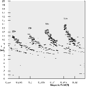
The same experiment can be repeated for an extracted ion beam,
scanning over higher values of the spectrometer magnetic field.
Figure 6 (b) illustrates such a scan for a 50 kV extracted tantalum
ion beam. In this case, each charge state appears as an almost
vertical line since the inherent plasma energy spread is superimposed
on the much higher energy gained from the extraction voltage.
Again the high charge states appear at the lower left of the
figure, and it can be seen that the early part of the extracted
current pulse (compare with Figure 3) does consist of around 10
high charge states from 23+ to 13+.
2.4 Beam emittance
The transverse emittance of an ion beam is a measure of
how the individual ion trajectories within the beam are distributed
in phase space3. Beam emittance is an important parameter
for the design of accelerating structures. The laser ion source
beam emittance has been measured using the "pepper-pot"
technique. A perforated metal foil, or pepper-pot, is placed
on the axis of the ion beam. The holes in the pepper-pot define
a series of positions in phase space; ions pass through the holes
and form an array of images on a micro-channel plate phosphor
screen. The size of these images gives a measure of the spread
in particle trajectory in the plane of the pepper-pot, and the
angular position of images is calculated from the geometry of
the system. The summation of this information from the whole
beam allows one to plot a phase space ellipse and calculate the
transverse beam emittance (the emittance equals the ellipse area
divided by p).


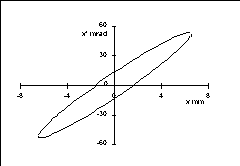
Figure 7 (a): CCD camera image of pepper-pot. 7 (b):
Phase space ellipse
Figure 7 (a) shows a CCD camera image of the pepper-pot array
seen on the micro-channel plate phosphor screen for a tantalum
ion beam. The pepper-pot consists of a 2 mm square array of
80 mm diameter
holes in a copper foil. The pepper-pot is mounted directly onto
rear side of the ground extraction electrode, so that the ion
beam is sampled before any appreciable space charge "blow-up"
takes place. The extraction voltage was 66 kV, and extraction
aperture diameter was 15 mm. Figure 7 (b) shows a phase space
ellipse calculated from this pepper-pot measurement, which yields
a value for the transverse emittance of 105 mm.mrad (5 rms).
Note that the micro-channel plate was pulsed, with the measurement
gate of 2 ms
duration timed to coincide with the peak of the high charge state
part of the current pulse. The emittance measured here thus includes
information on several different charge states (from 23+ to 13+)
which cannot be resolved.
2.5 Energy spread reduction - modulated extraction voltage
The rapid expansion of hot, dense plasma in a laser ion source
results in a range of kinetic energy being imparted to ions.
Normally, a DC extraction voltage is used to form the ion beam,
so ions in the beam exhibit the same energy spread as the particles
in the expanding plasma. In general, one is interested in accelerating
only ions of a single charge state, so a low energy beam transport
line (LEBT) is used to transport the chosen ions whilst also discarding
the unwanted charge states. The spread in ion energies results
in an undesirable increase in beam dimension introduced by the
chromatic aberration associated with the focusing or filtering
elements, and also makes acceleration by following RF structures
more difficult. The inherent spread in ion beam energy can be
reduced by modulating the extraction voltage in time, so that
the higher energy ions leaving the source earlier see a lower
extraction voltage than less energetic ions which emerge later.
The extraction voltage modulation circuit is shown in Figure
8 (a). A positive DC voltage of 60 kV is applied to the target
chamber, and a negative voltage of -7 kV is stored in capacitor
C. A thyratron trigger then discharges capacitor C to ground
through resistance R, which has the effect of superimposing a
voltage ramp of 7 kV with time constant t
= RC onto the DC extraction voltage. Figure
8 (b) shows an oscilloscope trace of such a voltage ramp with
C = 40 nF and R = 140 W
( t = 5.6
ms).
Figure 8 (a): Extraction voltage ramping circuit. 8 (b): Oscilloscope trace of extraction voltage ramp.
The trigger delay, time constant t,
and magnitude of the extraction voltage ramp are chosen to compensate
the energy spread measured for the ion beam with DC extraction
voltage. Figure 9 (a) shows a partial charge state distribution
(measured as described in section 2.3) for tantalum ions of charge
state 17+ to 20+, with a DC extraction voltage of 63 kV. The
range of magnetic field covered on the horizontal axis by each
charge state corresponds to its spread in momentum, from which
one can calculate the energy spread. In this case, the energy
spread DE/E
is about 11 %. Figure 9 (b) shows a corresponding partial charge
state distribution for a modulated extraction voltage. The extraction
voltage was modulated from 54.5 kV to 64.5 kV, in a ramp triggered
1.6 ms after
the laser pulse with time constant t
= 5.6 ms;
these conditions were chosen to overlap the voltage ramp with
the position of the signal seen for DC extraction. It can be
seen from Figure 9 (b) that each charge state extends over a
much smaller range of magnetic fields on the horizontal axis,
and the energy spread DE/E
for this modulated extraction voltage case is reduced to about
2.5 %.


voltage. Energy spread DE/E
= 11 %. voltage. Energy spread DE/E
= 2.5 %.
2.6 Accelerated light ion beam
Since the CERN accelerator system is concerned with heavy ions,
all the work reported here so far has been involved with tantalum
ions (as a practical experimental alternative to lead). However,
a series of experiments was carried out with aluminium ions to
make use of existing focusing elements and a radio frequency quadrupole
(RFQ) accelerator which were designed for light ions (the RFQ
was a contribution from the Lawrence Berkeley Laboratory to the
oxygen ion accelerator project at CERN)4. This work
was done in order to prove the principle that a laser-produced
ion beam could be contained and further accelerated. A schematic
diagram of the experimental set-up is shown in Figure 10.

Figure 10: Experimental set-up for aluminium ion beam
acceleration.
Very high currents are produced from targets of light elements,
so a long extraction drift distance of 2.2 m and small extraction
apertures of 10 mm diameter were chosen to restrict the ion beam
current. If too much current is extracted, there is a risk of
breakdown between the extraction electrodes. The light ion RFQ
was designed for particles with an input energy of 5.6 keV/u (i.e.
energy per nucleon), which dictated an extraction voltage of
15 kV for aluminium 10+ ions. The LEBT consists of two elements;
first an electrostatic Einzel lens to collimate the beam after
extraction, and secondly a pulsed magnetic solenoid lens to focus
the beam into the entrance of the RFQ. From a total current of
120 mA leaving the extraction system, the current at the entrance
to the RFQ was measured to be 5 mA, with the majority of the current
loss being due to space charge blow-up of the beam before it enters
the Einzel lens. The current after the RFQ was measured as 3
mA. Analysis with the magnetic spectrometer showed that aluminium
ions 9+ and 10+ had been successfully accelerated to 139 keV/u.
3.1 Source requirements for the CERN Large Hadron Collider
At present, lead ions are accelerated at CERN in the Super Proton
Synchrotron (SPS) for fixed target experiments, using an Electron
Cyclotron Resonance (ECR) ion source5. A schematic
diagram of the CERN heavy ion accelerator sequence is shown in
figure 11. The ECR source produces 80 mA
of lead 27+ ions in a long pulse of up to 1 ms duration. After
acceleration in an RFQ and a linear accelerator (linac), this
current pulse is multi-turn injected into the Proton Synchrotron
Booster (PSB). Each of the four storage rings of the PSB is sequentially
filled with 17 ion beam "buckets" of length 6 ms,
where further acceleration takes place before injection into the
Proton Synchrotron (PS). This process of multi-turn stacking
is only 50 % efficient, and combined with an inherent increase
of beam emittance results in a substantial loss of beam luminosity.
If the present ECR source were to be used to supply the Large
Hadron Collider (LHC) then electron cooling and accumulation of
the beam in the Low Energy Antiproton Ring (LEAR) would be required.
This is the scheme considered in the conceptual design of the
LHC6.

A possible alternative to this scheme may be a laser ion source
which could provide 6 mA of lead 25+ in a pulse of duration 6
ms. This would
allow single-turn injection, and would satisfy the luminosity
requirements of the LHC. Further requirements for such a source
would be 1 Hz repetition rate to give an LHC filling time of a
few minutes, and a high number of shots (106 ) without
any intervention to allow un-interrupted runs over several weeks.
3.2 Laser ion source design
Based on results obtained with the present experimental ion source
set-up, a laser ion source can be proposed to meet the above requirements
of the LHC and associated injector sequence. The first, most
fundamental requirement is the peak charge state of lead 25+ which
sets the laser power density required as 8 x 10¹² W/cm2.
The focal spot diameter chosen to achieve this power density
is a trade-off between a small spot size which requires the lowest
absolute laser energy, and a larger spot size which allows the
use of a longer focal length mirror for greater flexibility in
the design of the target illumination scheme. It is planned to
use a mirror of focal length 2.6 m, allowing the laser to be delivered
to the target via a "folded beam" path, with the focusing
mirror being protected from sputtered target material. This results
in a focal spot diameter of 200 mm,
which means the laser has to provide an 80 J pulse of 30 ns duration.
The ion beam pulse duration of 6 ms
required to match the PSB bucket timing sets the extraction drift
length at 2.6 m. The current required to satisfy the LHC luminosity
is 6 mA; to allow for some losses is transmission, an extraction
aperture of 34 mm diameter is chosen which should provide a pulse
of 10 mA of lead 25+. Table 1 lists the important parameters
of the proposed design.
The required laser energy is seen from Table 1 to be 80 J. It
was discussed in section 2.2 that a characteristic CO2
laser pulse consists of a fast initial spike followed by a long
tail, with approximately half the total energy contained in each
part. The energy contained in the tail of the pulse is effectively
wasted, as it contributes only to low charge state production
and evaporation. Further, if the laser has a highly non-Gaussian
transverse beam profile, then more energy is lost in the far-field
distribution in the focal plane. For these reasons, a master-oscillator
/ power amplifier laser design is proposed7. The master
oscillator should include a low pressure tube to select single
mode operation, and an electro-optical switch to prevent generation
of the pulse tail. This clean single pulse would then pass through
a telescope beam expander to the power amplifier. By using such
a system, it is estimated that to provide 80 J of useful
laser energy at the target, the total initial laser energy would
need to be 100 J.
Some practical points need to be taken into account in the design
of the target chamber. With every laser shot, the expanding plasma
strikes the inside walls of the target chamber and releases particles,
causing a pressure rise. The requirement for 1 Hz operation places
a high demand on the pumping capacity of the target chamber to
minimise this effect. The design of the target itself is influenced
by the requirement for up to 106 shots between interventions.
Typically, 20 laser shots can be made on a single target
position before the crater becomes too large and optimal focus
is lost, leading to lower charge state yield. The diameter of
this crater then determines how far the target has to be rotated
to provide a new clean surface, which in turn dictates the total
target area. In the present experimental set-up the laser pulse
tail contributes greatly to the size of the crater, so measurements
with the new tail-less laser pulse will be needed to finalise
this design.
The work described here has shown that a laser ion source
can provide a high current, short pulse heavy ion beam. Beam
parameters such as emittance and energy spread have been measured
and found to be acceptable in terms of beam transport and matching
into further accelerator elements. A light ion beam has been
successfully accelerated by an RFQ. A laser ion source design
has been proposed which could meet the requirements of a lead
ion source for the LHC. The next stage in the development of
the CERN laser ion source is the construction of a dedicated LEBT
and RFQ to demonstrate acceleration of a lead ion beam.
This work has been carried out at CERN in close collaboration
with the following institutes:
Institute for Theoretical and Experimental Physics (ITEP); Moscow, Russia
Troitsk Branch of the Kurchatov Institute (TRINITI); Troitsk, Russia
Institute of Physics, Academy of Science of the Czech Republic; Prague, Czech Republic
Institute of Plasma Physics and Laser Microfusion; Warsaw, Poland
Institute of Optoelectronics, University of Technology: Warsaw,
Poland
1. I. G. Brown, The physics and technology of ion sources, Chapter 14, J Wiley, New York, 1989.
2. K. N. Makarov, Yu. A. Satov and A. P. Strel'tsov, Sov. J. Theor. and Exp. Phys, 106 (12), p. 1649, 1994.
3. J. Buon, "Beam phase space and emittance", CERN Accelerator School - Fifth General Accelerator Physics Course, Ed: S. Turner, Vol I, p. 89, CERN 94 - 01, Geneva 1994.
4. B. H. Wolf, K. Leible, P. Spadtke, N. Angert, J. Klabunde, B. Langenbeck, R. A. Gough, J. Staples, R. Caylor, D. Howard, R. MacGill, J. Tanabee, "Performance of the oxygen injector for the CERN Linac 1", GSI-86-2, GSI Darmstadt, 1986.
5. N. Angert, M. P. Bourgarel, E. Brouzet, R. Cappi, D. Dekkers, J. Evans, G. Gelato, H. Haseroth, C. E. Hill, G. Hutter, J. Knott, H. Kugler, A. Lombardi, H. Lustig, E. Malwitz, F. Nitsch, G. Parisi, A. Pisent, U. Raich, U. Ratzinger, L. Riccati, A. Schempp, K. Schindl, H. Schonauer, P. Tetu, H. H. Umstatter, M. Van Rooij, D. Warner, M. Weiss, "CERN heavy-ion facility design report" CERN 93-01, Ed: D. Warner, CERN Geneva, 1993.
6. LHC Study Group, "The Large Hadron Collider, conceptual design", CERN AC 95-05 (LHC), Ed: P. Lefevre and T. Pettersson, CERN Geneva, 1995.
7. "Investigation of highly-charged heavy ion generation.
CO2 laser ion source design.", Final report of
annex to memorandum of understanding between the European Orgnaisation
for Nuclear Research (CERN) and the Institute for Laser Physics
(ILP), Troitsk, Moscow Region, 1995.
| back to home... | prepared by Richard Scrivens | 7th December 1999 |