Project Overview
General Information
 Uppsala University at CERN leaflet
The CTF3 Two-beam Test-stand
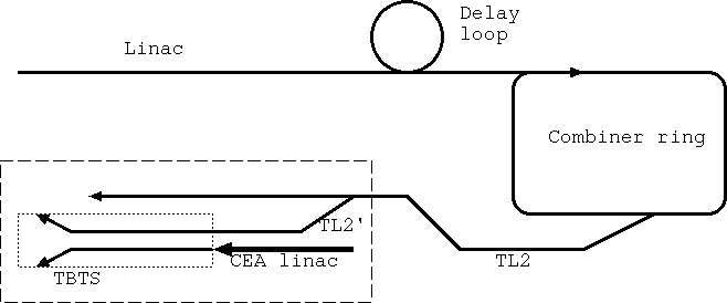
In CTF3 the two-beam acceleration scheme envisioned for CLIC will be tested
by first interleaving the bunches to obtain a bunch spacing corresponding to
the 12 GHz RF-frequency. Once the bunch-train with a length of about 100 ns
is available after the combiner ring it will be passed into the CTF3 experimental
hall (CLEX) where it will be transported through the TL2 and TL2' beam lines to
the drive-beam part of the Two-beam Test-stand, built by Uppsala University.
There 12 GHz RF-power will be generated in so-called PETS structures and
transported by wave-guides to the structures that will accelerate the parallel
running probe-beam part of the Two-beam Test-stand, also built by Uppsala University.
The probe-beam beam itself is provided by a 180 MeV electron LINAC built by our
colleagues at CEA in Saclay.
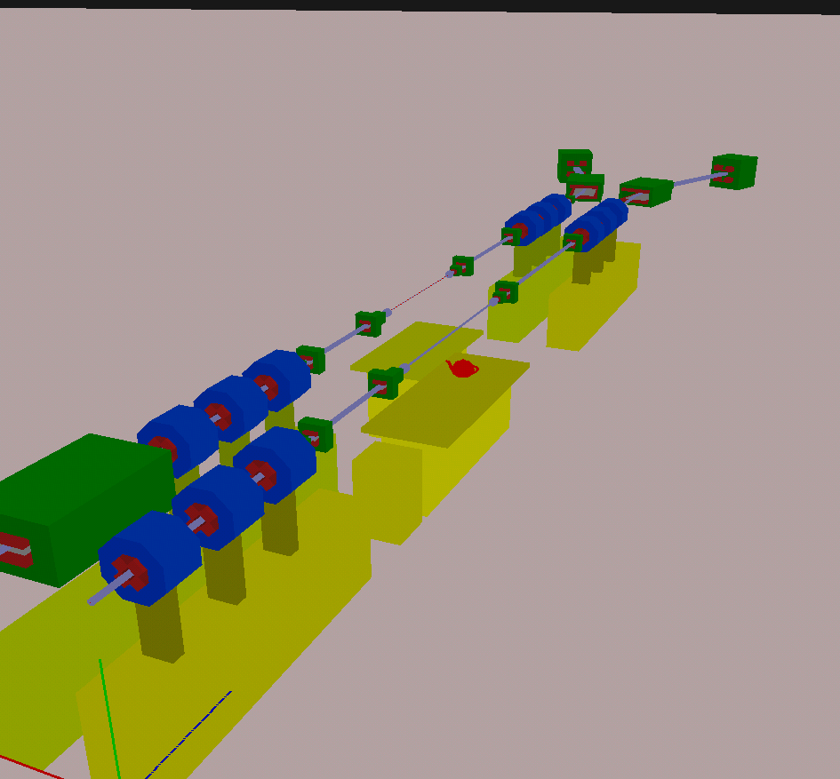
In the picture below we see the drive beam on the right hand and the
PETS decelerating structures will be located on the table with the
tea-pot. The parallel running probe-beam line is shown on the left.
The table in the center will hold the accelerating structures.
Up- and down-stream of the table are the quadrupoles shown in blue
that are needed to focus the beam into the RF-structures. The small
green dipole magnets are used to steer the beam and the large
dipole at the downstream end are used as specrometers to determine
the energy loss and gain of the drive and probe-beam, respectively.
|