| 8.3. The Visualization Drivers | ||
|---|---|---|
 | Chapter 8. Visualization |  |
| 8.3. The Visualization Drivers | ||
|---|---|---|
| | Chapter 8. Visualization | |
As explained in the Introduction to Visualization , Geant4 provides many different choices of visualization systems. Features and notes on each driver are briefly described here along with links to detailed web pages for the various drivers.
Details are given below for:
Table 8.1 lists required graphics systems and supported platforms for the various visualization drivers
| Driver | Required Graphics System | Platform |
| OpenGL-Xlib | OpenGL | Linux, UNIX, Mac with Xlib |
| OpenGL-Motif | OpenGL | Linux, UNIX, Mac with Motif |
| OpenGL-Win32 | OpenGL | Windows |
| Qt | Qt, OpenGL | Linux, UNIX, Mac, Windows |
| Wt | Wt for server side/Web browser for clients. | Linux, UNIX, Mac, Windows |
| OpenInventor-X | OpenInventor (Coin3D), OpenGL | Linux, UNIX, Mac with Xlib and Motif |
| OpenInventor-X-Extended | OpenInventor (Coin3D), OpenGL | Linux, UNIX, Mac with Xlib and Motif |
| OpenInventor-Win32 | OpenInventor, OpenGL | Windows |
| HepRep | HepRApp, FRED or WIRED4 HepRep Browser | Linux, UNIX, Mac, Windows |
| DAWNFILE | Fukui Renderer DAWN | Linux, UNIX, Mac, Windows |
| DAWN-Network | Fukui Renderer DAWN | Linux, UNIX |
| VRMLFILE | any VRML viewer | Linux, UNIX, Mac, Windows |
| VRML-Network | any network-enabled VRML viewer | Linux, UNIX |
| RayTracer | any JPEG viewer | Linux, UNIX, Mac, Windows |
| ASCIITree | none | Linux, UNIX, Mac, Windows |
| GAGTree | GAG | Linux, UNIX, Mac, Windows |
| XMLTree | any XML viewer | Linux, UNIX, Mac, Windows |
Table 8.1. Required graphics systems and supported platforms for the various visualization drivers.
These drivers have been developed by John Allison and Andrew Walkden (University of Manchester). It is an interface to the de facto standard 3D graphics library, OpenGL. It is well suited for real-time fast visualization and demonstration. Fast visualization is realized with hardware acceleration, reuse of shapes stored in a display list, etc. NURBS visualization is also supported.
Several versions of the OpenGL drivers are prepared. Versions for Xlib, Motif, Qt and Win32 platforms are available by default. For each version, there are two modes: immediate mode and stored mode. The former has no limitation on data size, and the latter is fast for visualizing large data repetitively, and so is suitable for animation.
Output can be exported to EPS (both vector and pixel graphics) using vis/ogl/printEPS.
More information can be found here : Section 8.4.14
If you want to open a OGL viewer, the generic way is :
/vis/open OGL
According to your G4VIS_USE... variables it will open the correct viewer. By default, it will be open in stored mode. You can specify to open an "OGLS" or "OGLI" viewer, or even "OGLSXm","OGLIXm",... If you don't have Motif or Qt, all control is done from Geant4 commands:
     /vis/open OGLIX
     /vis/viewer/set/viewpointThetaPhi 70 20
     /vis/viewer/zoom 2
     etc.
But if you have Motif libraries or Qt install, you can control Geant4 from Motif widgets or mouse with Qt:
/vis/open OGLSQt
The OpenGL driver added Smooth shading and Transparency since Geant4 release 8.0.
Further information (OpenGL and Mesa):
This driver has been developed by Laurent Garnier (IN2P3, LAL Orsay). It is an interface to the powerful application framework, Qt, now free on most platforms. This driver also requires the OpenGL library.
The Qt driver is well suited for real-time fast visualization and demonstration. Fast visualization is realized with hardware acceleration, reuse of shapes stored in a display list, etc. NURBS visualization is also supported. All OpenGL features are implemented in the Qt driver, but one also gets mouse control of rotation/translation/zoom, the ability to save your scene in many formats (both vector and pixel graphics) and an easy interface for making movies.
Two display modes are available: Immediate mode and Stored mode. The former has no limitation on data size, and the latter is fast for visualizing large data repetitively, and so is suitable for animation.
This driver has the feature to open a vis window into the UI window as a new tab. You can have as many tabs you want and mix them from Stored or Immediate mode. To see the visualization window in the UI :
     /vis/open OGL  (Generic way. For Stored mode if you have define your G4VIS_USE_QT variable)
or
     /vis/open OGLI  (for Immediate mode)
or
     /vis/open OGLS  (for Stored mode)
or
     /vis/open OGLIQt  (for Immediate mode)
or
     /vis/open OGLSQt  (for Stored mode)
Further information (Qt):
These drivers were developed by Jeff Kallenbach (FNAL) and Guy Barrand (IN2P3) based on the Hepvis class library originated by Joe Boudreau (Pittsburgh University). The OpenInventor drivers and the Hepvis class library are based on the well-established OpenInventor technology for scientific visualization. They have high extendibility. They support high interactivity, e.g., attribute e diting of picked objects. Some OpenInventor viewers support "stereoscopic" effects.
It is also possible to save a visualized 3D scene as an OpenInventor-formatted file, and re-visualize the scene afterwards.
Because it is connected directly to the Geant4 kernel, using same language as that kernel (C++), OpenInventor systems can have direct access to Geant4 data (geometry, trajectories, etc.).
Because OpenInventor uses OpenGL for rendering, it supports lighting and transparency.
OpenInventor provides thumbwheel control to rotate and zoom.
OpenInventor supports picking to ask about data. [Control Clicking] on a volume turns on rendering of that volume's daughters. [Shift Clicking] a daughter turns that rendering off: If modeling opaque solid, effect is like opening a box to look inside.
Further information (HEPVis and OpenScientist):
Further information (OpenInventor):
This driver was developed by Rastislav Ondrasek, Pierre-Luc Gagnon and Frederick Jones (TRIUMF). It extends the functionality of the OpenInventor driver, described in the previous section, by adding a number of new features to the viewer.
At present this driver is supported only on Linux/Unix/MacOS platforms and is not available for Windows. It requires the Coin3D implementation of OpenInventor.
All of the viewer functions and behavior of the basic OpenInventor driver are included and remain unchanged. The added viewer functions are implemented via dropdown menu items, buttons, a new navigation panel, and keyboard and mouse inputs.
Reference path navigation
Most of the added features are concerned with navigation along a "reference path" which is a piecewise linear path through the geometry. The reference path can be any particle trajectory, which may be chosen in the application by an attaching a visualization attribute to it, or at run time by selecting a trajectory with the mouse. Via Load and Save menu items, a reference path can be read from a file and the current reference path can be written to a file.
Once a reference path is established, the viewer pops up a Navigation Panel showing a list of all elements in the geometry, ordered by their "distance" along the reference path (based on the perpendicular from the element center to the path).
Navigation controls
[L,R,U,D refer to the arrow keys on the keyboard]
All these keys have a "repeat" function for continuous motion.
The rotation keys put the camera in a definite orientation, whereas The Shift-L and Shift-R keys can be used to "fly" along the path in whatever camera orientation is in effect. NOTE: if this appears to be "stuck", try switching from orthonormal camera to perspective camera ("cube" viewer button).
Menu Items:
Reference path animation
This is a special mode which flys the camera steadily along the path, without wraparound. The controls are:
For suitable geometries the U and D keys can be used to get "Star Wars" style fly-over and fly-under effects.
Bookmarks
At any time, the viewpoint and other camera parameters can be saved in a file as a labelled "bookmark". The view can then be restored later in the current run or in another run.
The default name for the bookmark file is ".bookmarkFile" The first time a viewpoint is saved, this file will be created if it does not already exist. When the viewer is first opened, it will automatically read this file if present and load the viewpoints into the left-hand panel of the viewer's auxiliary window.
Controls:
Special picking modes
Controls:
Convenience feature
It is now possible to escape from the Open Inventor viewer without using the mouse.
In addition to the File - Escape menu item, pressing the "e" key on the keyboard will exit from the viewer's X event loop. The viewer will become inactive and control will return to the Geant4 UI prompt.
The HepRepFile driver creates a HepRep XML file in the HepRep1 format suitable for viewing with the HepRApp HepRep Browser.
The HepRep graphics format is further described at http://www.slac.stanford.edu/~perl/heprep .
To write just the detector geometry to this file, use the command:
/vis/viewer/flush
Or, to also include trajectories and hits (after the appropriate /vis/viewer/add/trajectories or /vis/viewer/add/hits commands), just issue:
/run/beamOn 1
HepRepFile will write a file called G4Data0.heprep to the current directory. Each subsequent file will have a file name like G4Data1.heprep, G4Data2.heprep, etc.
View the file using the HepRApp HepRep Browser, available from:
http://www.slac.stanford.edu/~perl/HepRApp/ .
HepRApp allows you to pick on volumes, trajectories and hits to find out their associated HepRep Attributes, such as volume name, particle ID, momentum, etc. These same attributes can be displayed as labels on the relevant objects, and you can make visibility cuts based on these attributes ("show me only the photons", or "omit any volumes made of iron").
HepRApp can read heprep files in zipped format as well as unzipped, so you can save space by applying gzip to the heprep file. This will reduce the file to about five percent of its original size.
Several commands are available to override some of HepRepFile's defaults
You can specify a different directory for the heprep output files by using the setFileDir command, as in:
/vis/heprep/setFileDir <someOtherDir/someOtherSubDir>
You can specify a different file name (the part before the number) by using the setFileName command, as in:
/vis/heprep/setFileName <my_file_name>
which will produce files named <my_file_name>0.heprep, <my_file_name>1.heprep, etc.
You can specify that each file should overwrite the previous file (always rewriting to the same file name) by using the setOverwrite command, as in:
/vis/heprep/setOverwrite true
This may be useful in some automated applications where you always want to see the latest output file in the same location.
Geant4 visualization supports a concept called "culling", by which certain parts of the detector can be made invisible. Since you may want to control visibility from the HepRep browser, turning on visibility of detector parts that had defaulted to be invisible, the HepRepFile driver does not omit these invisible detector parts from the HepRep file. But for very large files, if you know that you will never want to make these parts visible, you can choose to have them left entirely out of the file. Use the /vis/heprep/setCullInvisibles command, as in:
/vis/heprep/setCullInvisibles true
Further information:
http://geant4.slac.stanford.edu/Presentations/vis/G4HepRAppTutorial/G4HepRAppTutorial.html
The HepRepXML driver creates a HepRep file in the HepRep2 format suitable for viewing with the WIRED4 Plugin to the JAS3 Analysis System or the FRED event display.
This driver can write both Binary HepRep (.bheprep) and XML HepRep (.heprep) files. Binary HepRep files are a one-to-one translation of XML HepRep files, but they are considerably shorter and faster to parse by a HepRepViewer such as WIRED 4.
Both Binary HepRep and XML HepRep can be compressed using the standard zlib library if linked into Geant4 using G4LIB_USE_ZLIB. If a standard zlib is not available (WIN32-VC for instance) you should also set G4LIB_BUILD_ZLIB to build G4zlib included with Geant4.
HepRep files (Binary and XML) can contain multiple HepRep events/geometries. If the file contains more than one HepRep it is not strictly XML anymore. Files can be written in .heprep.zip, .heprep.gz or .heprep format and their binary versions .bheprep.zip, .bheprep.gz or .bheprep.
The .heprep.zip is the default for file output, the .heprep is the default for stdout and stderr.
(Optional) To set the filename with a particular extension such as: .heprep.zip, .heprep.gz, .heprep, .bheprep.zip, .bheprep.gz or .bheprep use for instance:
/vis/scene/create filename.bheprep.zip
(Optional) To create separate files for each event, you can set a suffix such as "-0001" to start writing files from filename-0001.bheprep.zip to filename-9999.bheprep.zip (or up), while "-55-sub" will start write files filename-55-sub.bheprep.zip to filename-99-sub.bheprep.zip (or up).
/vis/heprep/setEventNumberSuffix -0001
(Note: suffix has to contain at least one digit)
(Optional) To route the HepRep XML output to stdout (or stderr), by default uncompressed, use:
/vis/scene/create stdout
(Optional) To add attributes to each point on a trajectory, use:
/vis/heprep/addPointAttributes 1
Be aware that this may increase the size of the output dramatically.
(Optional) You may use the commands:
     /vis/viewer/zoom                            to set an initial zoom factor

     /vis/viewer/set/viewpointThetaPhi           to set an initial view point

     /vis/heprep/setCoordinateSystem uvw         to change the coordinate system, where uvw
                                                 can be "xyz", "zxy", ...
(Optional) You may decide to write .zip files with events and geometry separated (but linked). This results in a smaller zip file, as the geometry is only written once. Use the command:
/vis/heprep/appendGeometry false
(Optional) To close the file, remove the SceneHandler, use:
/vis/sceneHandler/remove scene-handler-0
Limitations: Only one SceneHandler can exist at any time, connected to a single Viewer. Since the HepRep format is a model rather than a view this is not a real limitation. In WIRED 4 you can create as many views (SceneHandlers) as you like.
Further information:
The DAWN drivers are interfaces to Fukui Renderer DAWN, which has been developed by Satoshi Tanaka, Minato Kawaguti et al (Fukui University). It is a vectorized 3D PostScript processor, and so well suited to prepare technical high quality outputs for presentation and/or documentation. It is also useful for precise debugging of detector geometry. Remote visualization, off-line re-visualization, cut view, and many other useful functions of detector simulation are supported. A DAWN process is automatically invoked as a co-process of Geant4 when visualization is performed, and 3D data are passed with inter-process communication, via a file, or the TCP/IP socket.
When Geant4 Visualization is performed with the DAWN driver, the
visualized view is automatically saved to a file named
g4.eps in the current directory, which describes a
vectorized (Encapsulated) PostScript data of the view.
There are two kinds of DAWN drivers, the DAWNFILE driver and the DAWN-Network driver. The DAWNFILE driver is usually recommended, since it is faster and safer in the sense that it is not affected by network conditions.
The DAWNFILE driver sends 3D data to DAWN via an intermediate
file, named g4.prim in the current directory. The file
g4.prim can be re-visualized later without the help of
Geant4. This is done by invoking DAWN by hand:
% dawn g4.prim
DAWN files can also serve as input to two additional programs:
A standalone program, DAWNCUT, can perform a planar cut on a DAWN image. DAWNCUT takes as input a .prim file and some cut parameters. Its output is a new .prim file to which the cut has been applied.
Another standalone program, DAVID, can show you any volume overlap errors in your geometry. DAVID takes as input a .prim file and outputs a new .prim file in which overlapping volumes have been highlighted. The use of DAVID is described in section Section 4.1.11 of this manual.
The DAWN-Network driver is almost the same as the DAWNFILE driver except that
If you have not set up network configurations of your host machine,
set the environment variable G4DAWN_NAMED_PIPE to "1",
e.g., % setenv G4DAWN_NAMED_PIPE 1. This setting switches
the default socket connection to the named-pipe connection within
the same host machine. The DAWN-Network driver also saves the 3D
data to the file g4.prim in the current directory.
Visualization in Geant4 is considered to be "remote" when it is performed on a machine other than the Geant4 host. Some of the visualization drivers support this feature.
Usually, the visualization host is your local host, while the
Geant4 host is a remote host where you log in, for example, with
the telnet command. This enables distributed
processing of Geant4 visualization, avoiding the transfer of large
amounts of visualization data to your terminal display via the
network. This section describes how to perform remote Geant4
visualization with the DAWN-Network driver. In order to do it,
you must install the Fukui Renderer DAWN on your local host
beforehand.
The following steps realize remote Geant4 visualization viewed by DAWN.
Invoke DAWN with "-G" option on your local host:
Local_Host> dawn -G
This invokes DAWN with the network connection mode.
Login to the remote host where a Geant4 executable is placed.
Set an environment variable on the remote host as follows:
Remote_Host> setenv G4DAWN_HOST_NAME local_host_name
For example, if you are working in the local host named "arkoop.kek.jp", set this environment variable as follows:
Remote_Host> setenv G4DAWN_HOST_NAME arkoop.kek.jp
This tells a Geant4 process running on the remote host where Geant4 Visualization should be performed, i.e., where the visualized views should be displayed.
Invoke a Geant4 process and perform visualization with the DAWN-Network driver. For example:
       Idle> /vis/open DAWN
       Idle> /vis/drawVolume
       Idle> /vis/viewer/flush
In step 4, 3D scene data are sent from the remote host to the
local host as
DAWN-formatted data, and the local DAWN will visualize the data. The
transferred data are saved as a file named g4.prim in the
current directory of the local host.
Further information:
Further information:
These drivers were developed by Satoshi Tanaka and Yasuhide Sawada (Fukui University). They generate VRML files, which describe 3D scenes to be visualized with a proper VRML viewer, at either a local or a remote host. It realizes virtual-reality visualization with your WWW browser. There are many excellent VRML viewers, which enable one to perform interactive spinning of detectors, walking and/or flying inside detectors or particle showers, interactive investigation of detailed detector geometry etc.
There are two kinds of VRML drivers: the VRMLFILE driver, and the VRML-Network driver. The VRMLFILE driver is usually recommended, since it is faster and safer in the sense that it is not affected by network conditions.
The VRMLFILE driver sends 3D data to your VRML viewer, which is
running on the same host machine as Geant4, via an intermediate
file named g4.wrl created in the current directory. This
file can be re-visualization afterwards. In visualization, the name
of the VRML viewer should be specified by setting the environment
variable G4VRML_VIEWER beforehand. For example,
% setenv G4VRML_VIEWER "netscape"
Its default value is NONE, which means that no viewer
is invoked and only the file g4.wrl is generated.
Visualization in Geant4 is considered to be "remote" when it is performed on a machine other than the Geant4 host. Some of the visualization drivers support this feature.
Usually, the visualization host is your local host, while the
Geant4 host is a remote host where you log in, for example, with
the telnet command. This enables distributed processing of
Geant4 visualization, avoiding the transfer of large amounts of
visualization data to your terminal display via the network.
In order to perform remote visualization with the VRML-Network driver, the following must be installed on your local host beforehand:
g4vrmlview.
The Java application g4vrmlview is included as part of the
Geant4 package and is located at:
source/visualization/VRML/g4vrmlview/
Installation instructions for g4vrmlview can be found in
the README file there, or on the WWW page below.
The following steps realize remote Geant4 visualization displayed with your local VRML browser:
Invoke the g4vrmlview on your local host, giving a
VRML viewer name as its argument:
Local_Host> java g4vrmlview VRML_viewer_name
For example, if you want to use the Netscape browser as your VRML
viewer, execute g4vrmlview as follows:
Local_Host> java g4vrmlview netscape
Of course, the command path to the VRML viewer should be properly set.
Log in to the remote host where a Geant4 executable is placed.
Set an environment variable on the remote host as follows:
Remote_Host> setenv G4VRML_HOST_NAME local_host_name
For example, if you are working on the local host named "arkoop.kek.jp", set this environment variable as follows:
Remote_Host> setenv G4VRML_HOST_NAME arkoop.kek.jp
This tells a Geant4 process running on the remote host where Geant4 Visualization should be performed, i.e., where the visualized views should be displayed.
Invoke a Geant4 process and perform visualization with the VRML-Network driver. For example:
       Idle> /vis/open VRML2
       Idle> /vis/drawVolume
       Idle> /vis/viewer/update
In step 4, 3D scene data are sent from the remote host to the
local host as VRML-formatted data, and the VRML viewer specified in
step 3 is invoked by the g4vrmlview process to visualize
the VRML data. The transferred VRML data are saved as a file named
g4.wrl in the current directory of the local host.
Further information:
Further information (VRML drivers):
Sample VRML files:
Further information (VRML language and browsers):
This driver was developed by Makoto Asai and Minamimoto (Hirosihma Instutute of Technology). It performs ray-tracing visualization using the tracking routines of Geant4. It is, therefore, available for every kinds of shapes/solids which Geant4 can handle. It is also utilized for debugging the user's geometry for the tracking routines of Geant4. It is well suited for photo-realistic high quality output for presentation, and for intuitive debugging of detector geometry. It produces a JPEG file. This driver is by default listed in the available visualization drivers of user's application.
Some pieces of geometries may fail to show up in other visualization drivers (due to algorithms those drivers use to compute visualizable shapes and polygons), but RayTracer can handle any geometry that the Geant4 navigator can handle.
Because RayTracer in essence takes over Geant4's tracking routines for its own use, RayTracer cannot be used to visualize Trajectories or hits.
An X-Window version, called RayTracerX, can be selected by
setting GEANT4_USE_RAYTRACER_X11 (for CMake) at Geant4 library
build time and application (user
code) build time (assuming you use the standard visualization
manager, G4VisExecutive, or an equally smart vis manager).
RayTracerX builds the same jpeg file as RayTracer, but
simultaneously renders to screen so you can watch as rendering
grows progressively smoother.
RayTracer has its own built-in commands -
/vis/rayTracer/.... Alternatively, you can treat it as a
normal vis system and use /vis/viewer/... commands,
e.g:
  /vis/open RayTracerX
  /vis/drawVolume
  /vis/viewer/set/viewpointThetaPhi 30 30
  /vis/viewer/refresh
The view parameters are translated into the necessary RayTracer parameters.
RayTracer is compute intensive. If you are unsure of a good
viewing angle or zoom factor, you might be advised to choose them
with a faster renderer, such as OpenGL, and transfer the view
parameters with /vis/viewer/copyViewFrom:
  /vis/open OGL
  /vis/drawVolume
  /vis/viewer/zoom  # plus any /vis/viewer/commands that get you the view you want.
  /vis/open RayTracerX
  /vis/viewer/copyViewFrom viewer-0
  /vis/viewer/refresh
The gMocrenFile driver creates a gdd file suitable for viewing with the gMocren volume visualizer. gMocren, a sophisticated tool for rendering volume data, can show volume data such as Geant4 dose distrubutions overlaid with scoring grids, trajectories and detector geometry. gMocren provides additional advanced functionality such as transfer functions, colormap editing, image rotation, image scaling, and image clipping.
gMocren is further described at http://geant4.kek.jp/gMocren/ . At this link you will find the gMocren download, the user manual, a tutorial and some example gdd data files.
Please note that the gMocren file driver is currently considered a Beta release. Users are encouraged to try this driver, and feedback is welcome, but users should be aware that features of this driver may change in upcoming releases.
To send volume data from Geant4 scoring to a gMocren file, the user needs to tell the gMocren driver the name of the specific scoring volume that is to be displayed. For scoring done in C++, this is the name of the sensitive volume. For command-based scoring, this is the name of the scoring mesh.
/vis/gMocren/setVolumeName <volume_name>
The following is an example of the minimum command sequence to send command-based scoring data to the a gMocren file:
    # an example of a command-based scoring definition
    /score/create/boxMesh scoringMesh       # name of the scoring mesh
    /score/mesh/boxSize 10. 10. 10. cm      # dimension of the scoring mesh
    /score/mesh/nBin 10 10 10               # number of divisions of the scoring mesh
    /score/quantity/energyDeposit eDep      # quantity to be scored
    /score/close
    # configuration of the gMocren-file driver
    /vis/scene/create
    /vis/open gMocrenFile
    /vis/gMocren/setVolumeName scoringMesh
To add detector geometry to this file:
/vis/viewer/flush
To add trajectories and primitive scorer hits to this file:
    /vis/scene/add/trajectories
    /vis/scene/add/pshits
    /run/beamOn 1
gMocrenFile will write a file named G4_00.gd to the current directory. Subsequent draws will create files named g4_01.gdd, g4_02.gdd, etc. An alternate output directory can be specified with an environment variable:
export G4GMocrenFile_DEST_DIR=<someOtherDir/someOtherSubDir/>
View the resuling gMocren files with the gMocren viewer, available from: http://geant4.kek.jp/gMocren/ .
This driver has been developed by Laurent Garnier (IN2P3, LAL Orsay). It provide an interface to a geant4 application inside a Web browser. This driver also requires the Wt library and a Web browser with WebGL enable. See if your Web browser support WebGL on Wikipedia#WebGL#Support
The Wt driver is well suited for real-time fast visualization and demonstration. Available as experimental in Geant4.10 version, all OpenGL features are not implemented but basics interactions as mouse control of rotation/translation/zoom are present.
Wt driver rely on WebGL, it aims to render the same way as Qt, but inside a Web browser. The use of WebGL (instead of OpenGL for Qt), allow it to be available wherever a Web browser with WebGL is activate.
Sources files:
See CMake configuration in order to compile Geant4 with Wt support.
As a Geant4 with Wt driver application will be available inside a Web browser, your need at first to launch a web server in order to be able to see the web page. Hopefully, Wt came with its own web server included. This web server will be multi-user, that means that you could have many users using your application from everywhere. As the support for Wt driver is experimental, the multi-user aspect is not well manage. In Geant4.10, many users will have access at the same Run manager at the same time and evn to the files and datas, this could cause some troubles.
As a Geant4 application using Wt driver is a client/server application, the way to build the main function is a bit different.
Example 8.4.
The typical main() routine available for visualization with Wt driver.
 //----- C++ source codes: main() function for visualization
 #ifdef G4VIS_USE
 #include "G4VisExecutive.hh"
 #endif

  // Wt includes
 #if defined(G4UI_USE_WT)
 #include <Wt/WApplication>
 #include <Wt/WEnvironment>
 #include <Wt/WServer>


 // Main Wt driver function. It will be call once by user launching the application
 // Inside this function, you have to put all your Geant4 initialisation
 // (as in main() function on other graphic drivers)
 Wt::WApplication *createApplication(const Wt::WEnvironment& env)
 {

  // Create a new instance of Wt::Application
  Wt::WApplication* myApp = new Wt::WApplication(env);

  // Set title and styleSheet
  wApp->setTitle( "Geant4 on the web" );
  wApp->useStyleSheet("extkitchen.css");


  // Get the pointer to the User Interface manager
  G4UImanager* UImanager = G4UImanager::GetUIpointer();

  char* name = "ExampleN03 \0";
  G4UIExecutive* ui = new G4UIExecutive(1,&name, "Wt");

  // Start the session
  ui->SessionStart();
  delete ui;

  return myApp;
 }
#endif


 int main(int argc,char** argv) {

 .....

   // Instantiation and initialization of the Visualization Manager
 #ifdef G4VIS_USE
   // visualization manager
   G4VisManager* visManager = new G4VisExecutive;
   // G4VisExecutive can take a verbosity argument - see /vis/verbose guidance.
   // G4VisManager* visManager = new G4VisExecutive("Quiet");
   visManager->Initialize();
 #endif

 .....

 // replace the "normal" user interface by the Web server
 #ifndef G4UI_USE_WT
  // Get the pointer to the User Interface manager
  G4UImanager* UImanager = G4UImanager::GetUIpointer();
 #else
  try {
    // Create a Wt::WServer
    Wt::WServer server(argv[0]);

    server.setServerConfiguration(argc, argv, WTHTTP_CONFIGURATION);

    server.addEntryPoint(Wt::Application, createApplication);

    // Run it !
    if (server.start()) {
      int sig = Wt::WServer::waitForShutdown();

      server.stop();
    }
  } catch (Wt::WServer::Exception& e) {
    std::cerr << e.what() << "\n";
    return 1;
  } catch (std::exception& e) {
    std::cerr << "exception: " << e.what() << "\n";
    return 1;
  }

  // Wait for clients
  Wt::WRun(argc, argv, &createApplication);

  // Job termination
  #ifdef G4VIS_USE
   delete visManager;
 #endif

 .....
 #endif

  return 0;
 }

 //----- end of C++
This driver will display the UI and vis window inside a Web browser page. As with Qt driver, you can have as many tabs with viewer you want. To see the visualization window :
     /vis/open OGL
other parameters as OGLI, OGLS, OGLIWt, OGLSWt will have all the same effect
Execution of the server: As your application will contain a web server, you will have to launch the web server first and set some specific arguments for internet :
More informations on Wt web site The command line for launching your application will be the following :
myExample --docroot "where your ressources are" --http-address 0.0.0.0 --http-port 8080
Execution of a client: All clients can reach your application server at the following address :
http://0.0.0.0:8080 (for users on the same computer as the server)
http://Your.Server.Ip:8080 (for external users)
If this address is unreachable, check if the specify port is not already in use and is fully open.
Further information (Wt):
ASCIITREE is a visualization driver that is not actually graphical but that dumps the volume hierarchy as a simple text tree.
Each call to /vis/viewer/flush or /vis/drawTree will dump the tree.
ASCIITree has command to control its verbosity,
/vis/ASCIITree/verbose. The verbosity value controls the
amount of information available, e.g., physical volume name alone,
or also logical volume and solid names. If the volume is
"sensitive" and/or has a "readout geometry", this may also be
indicated. Also, the mass of the physical volume tree(s) can be
printed (but beware - higher verbosity levels can be
computationally intensive).
At verbosity level 4, ASCIITree calculates the mass of the complete geometry tree taking into account daughters up to the depth specified for each physical volume. The calculation involves subtracting the mass of that part of the mother that is occupied by each daughter and then adding the mass of the daughter, and so on down the hierarchy.
     /vis/ASCIITree/Verbose 4
     /vis/viewer/flush
     "HadCalorimeterPhysical":0 / "HadCalorimeterLogical" / "HadCalorimeterBox"(G4Box),
                                  1.8 m3 , 11.35 g/cm3
     "HadCalColumnPhysical":-1 (10 replicas) / "HadCalColumnLogical" / "HadCalColumnBox"(G4Box),
                                               180000 cm3, 11.35 g/cm3
     "HadCalCellPhysical":-1 (2 replicas) / "HadCalCellLogical" / "HadCalCellBox"(G4Box),
                                            90000 cm3, 11.35 g/cm3
     "HadCalLayerPhysical":-1 (20 replicas) / "HadCalLayerLogical" / "HadCalLayerBox"(G4Box),
                                              4500 cm3, 11.35 g/cm3
     "HadCalScintiPhysical":0 / "HadCalScintiLogical" / "HadCalScintiBox"(G4Box),
                                900 cm3, 1.032 g/cm3

     Calculating mass(es)...
     Overall volume of "worldPhysical":0, is 2400 m3
     Mass of tree to unlimited depth is 22260.5 kg
Some more examples of ASCIITree in action:
     Idle> /vis/ASCIITree/verbose 1
     Idle> /vis/drawTree
     #  Set verbosity with "/vis/ASCIITree/verbose "
     #    <  10: - does not print daughters of repeated placements, does not repeat replicas.
     #    >= 10: prints all physical volumes.
     #  The level of detail is given by verbosity%10:
     #  for each volume:
     #    >=  0: physical volume name.
     #    >=  1: logical volume name (and names of sensitive detector and readout geometry, if any).
     #    >=  2: solid name and type.
     #    >=  3: volume and density.
     #    >=  5: daughter-subtracted volume and mass.
     #  and in the summary at the end of printing:
     #    >=  4: daughter-included mass of top physical volume(s) in scene to depth specified.
     .....
     "Calorimeter", copy no. 0, belongs to logical volume "Calorimeter"
       "Layer", copy no. -1, belongs to logical volume "Layer" (10 replicas)
         "Absorber", copy no. 0, belongs to logical volume "Absorber"
           "Gap", copy no. 0, belongs to logical volume "Gap"
     .....
     Idle> /vis/ASCIITree/verbose 15
     Idle> /vis/drawTree
     ....
      "tube_phys":0 / "tube_L" / "tube"(G4Tubs), 395841 cm3, 1.782 mg/cm3,
                                9.6539e-08 mm3, 1.72032e-10 mg
        "divided_tube_phys":0 / "divided_tube_L" / "divided_tube"(G4Tubs), 65973.4 cm3,
                                1.782 mg/cm3, 7587.54 cm3, 13.521 g
          "divided_tube_inset_phys":0 / "divided_tube_inset_L" / "divided_tube_inset"(G4Tubs),
                                        58385.9 cm3, 1.782 mg/cm3, 6.03369e-09 mm3, 1.0752e-11 mg
            "sub_divided_tube_phys":0 / "sub_divided_tube_L" / "sub_divided_tube"(G4Tubs),
                                        14596.5 cm3, 1.782 mg/cm3, 12196.5 cm3, 21.7341 g
     .....
     Calculating mass(es)...
     Overall volume of "expHall_P":0, is 8000 m3  and the daughter-included mass to unlimited depth
                                      is 78414 kg
     .....
For the complete list of commands and options, see the Control...UICommands section of this user guide.
The GAGTree driver provides a listing of the detector geometry tree
within GAG, the Geant Adaptive GUI, from the environments/MOMO/MOMO.jar file present under the Geant4 source distribution.
GAG allows "folding/un-folding" a part of the geometry tree, using
the Tree Widget in Java:
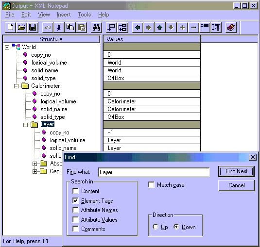
The XML description of the geometry tree can be created in Geant4 by the XML Tree driver. The XML source can also be edited on the fly. The created XML files are visualizable with any XML browser (in Windows, a good XML viewer is XML Notepad).
| |  | |
| 8.2. Adding Visualization to Your Executable |  | 8.4. Controlling Visualization from Commands |