Public Liquid-Argon Calorimeter Plots on Upgrade
Introduction
The LAr Upgrade simulation plots below are approved to be shown by ATLAS speakers at conferences and similar events. Please do not add figures on your own. Contact the LAr project leader in case of questions and/or suggestions.Phase I Upgrade Plots
The plots from the LAr Phase I Upgrade TDRDemonstrator for the ATLAS LAr calorimeter Phase I Trigger Readout Upgrade
Two LAr Phase I trigger upgrade demonstrator boards (2 Demonstrator LTDBs, LAr Trigger Digitizer Boards) were installed in-situ on the LAr detector in July 2014 (coverage: 9π/16 < φ < 11π/16, 0 < η < 1.4). To receive the digital super-cell energies ABBA boards (LDPB pre-prototype) were installed in USA15. One ABBA board receives data from one LTDB 320 super cells. Super-cell data has been recorded for a large number of time slices with this pre-prototype backend electronics.Data from 2017 runs: Energy comparison, timing resolution, overview plots and shower properties
General Information- The plots show data from pp collisions, physics run 334487, recorded on August 30, 2017.
- Events were triggered by dedicated triggers requiring either a Level 1 electromagnetic cluster (EM) with ET > 20 GeV or a Level 1 Jet with ET > 100 GeV within the demonstrator acceptance (for EM (Jet) 1.6 < φ < 2.2 (2.3), 0 < η < 1.5). Those triggers were prescaled to have a combined event rate of approximately 1 Hz.
- Events from the LAr demonstrator are matched to events collected in the main read-out using their bunch-crossing ID and brunch-crossing time. An alternative method is the matching according to the L1 ID of the events.
- Two different prototypes of LAr Trigger Digitizer boards (LTDBs) were installed: The first for the region φ = 1.81 and φ = 1.91; the other for φ = 2.01 and φ = 2.11. This leads to different calibration and also slightly different results for those two regions.
- Energy and timing resolution of demonstrator system
- All events for given supercell that satisfy |Edem - Emain | / Emain < 0.5 and Emain > 2 GeV are used.
- The events are then further separated into 15 bins with equal statistics. For each of these bins the mean and RMS value is obtained.
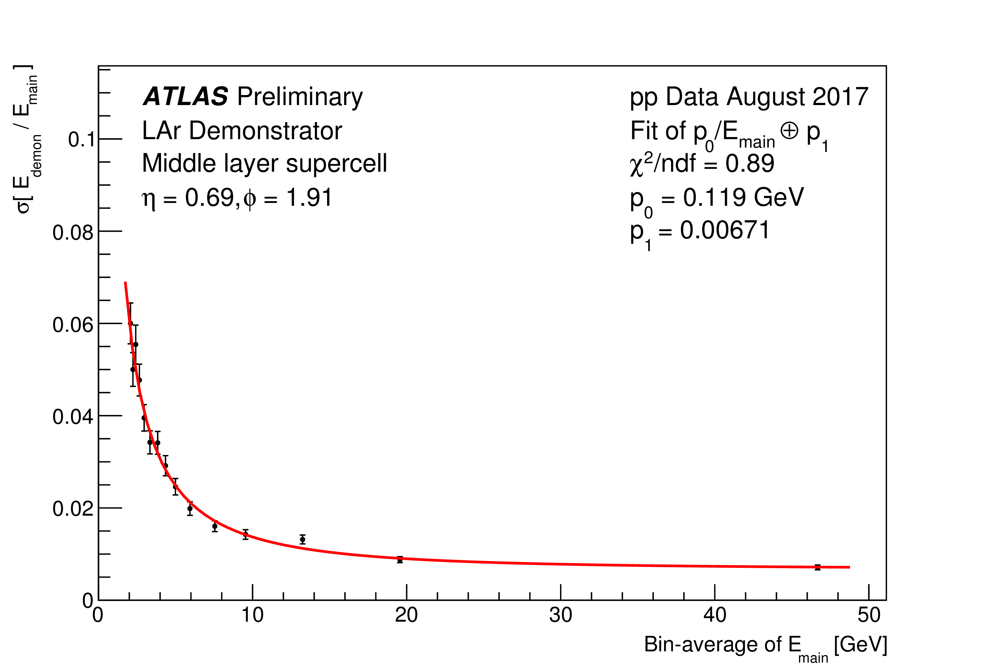
- The chosen functional parametrisation for the energy resolution is given by σ/E = b/E ⊕ c and thus neglects the stochastic (shower) component (∝ 1/E0.5), as the resolution is obtained from a ratio of the two read-outs and thus both are affected in the same way by the shower fluctuations.
- The functional parametrisation for the timing resolution is chosen to match the public plots from the main read-out.
- Overview of mean and RMS values for energy and timing distributions
- Out of all events with |Edem - Emain | / Emain < 0.5 and Emain > 2 GeV are used, only the 20% highest energy deposits are used. &to; Same requirement as for plots in next section.
- The mean and RMS values are then obtained and plotted for each layer.
- Comparison of the shower modelling
- Supercell with highest energy in shower fulfils Emain > 20 GeV and |Edem - Emain | / Emain < 0.1.
- Other supercells are considered if they fulfil |Edem - Emain | / Emain < 0.8 and Escell > 1% Emax.
- The two above criteria largely resemble the selection used to extract event displays.
- Shower cone defined as supercells within |φ - φmax | < 0.15 (three iphi layers) and |η - ηmax | < 0.05 (width of a trigger tower) of maximum energy deposit.
- The shower shape variables are defined in the LAr Phase I Upgrade TDR
 as follows (with E(i) as the energy measured in the i-th layer):
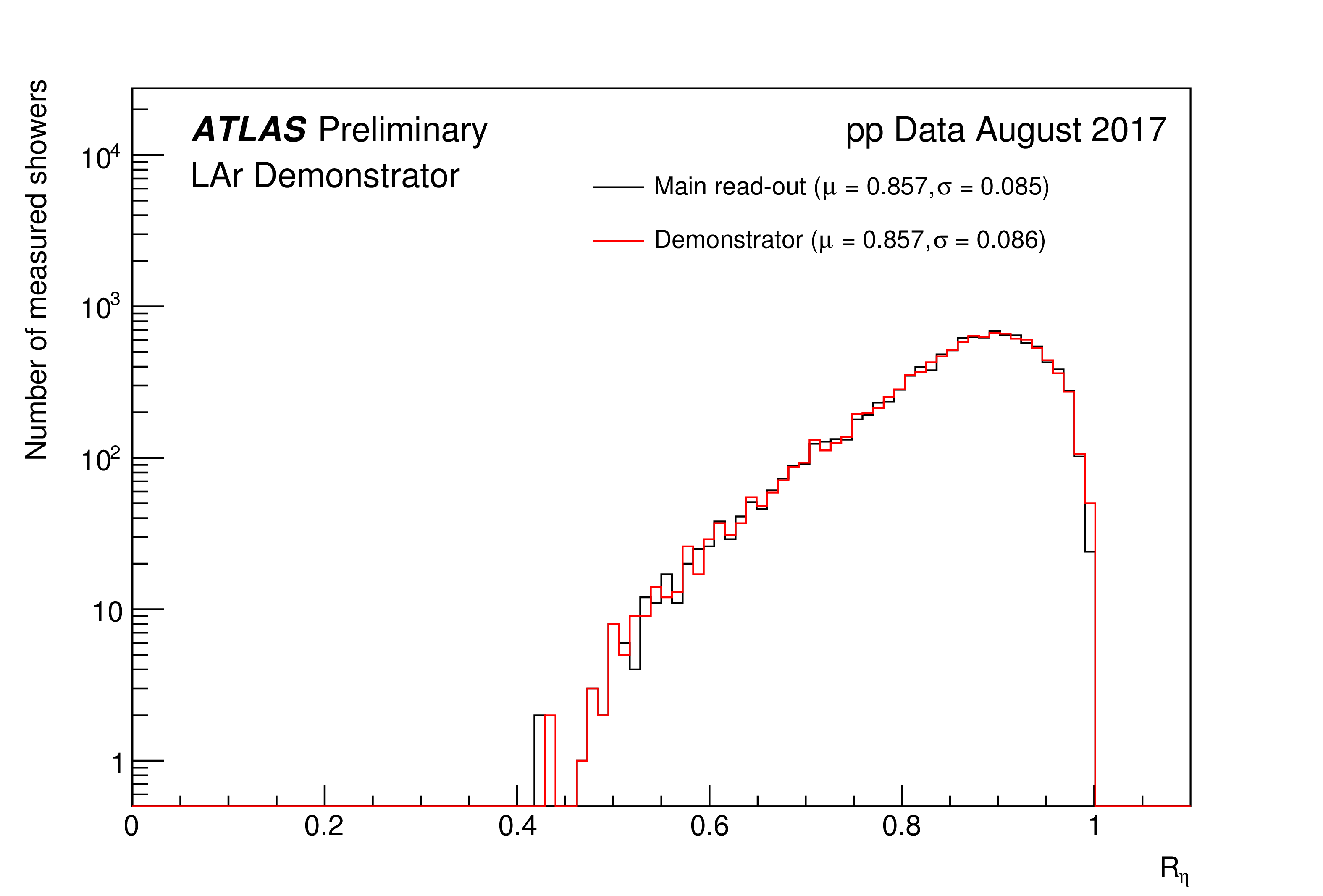
Rη = (E(2)T,Δη×Δφ=0.075×0.2)/(E(2)T,Δη×Δφ=0.175×0.2)
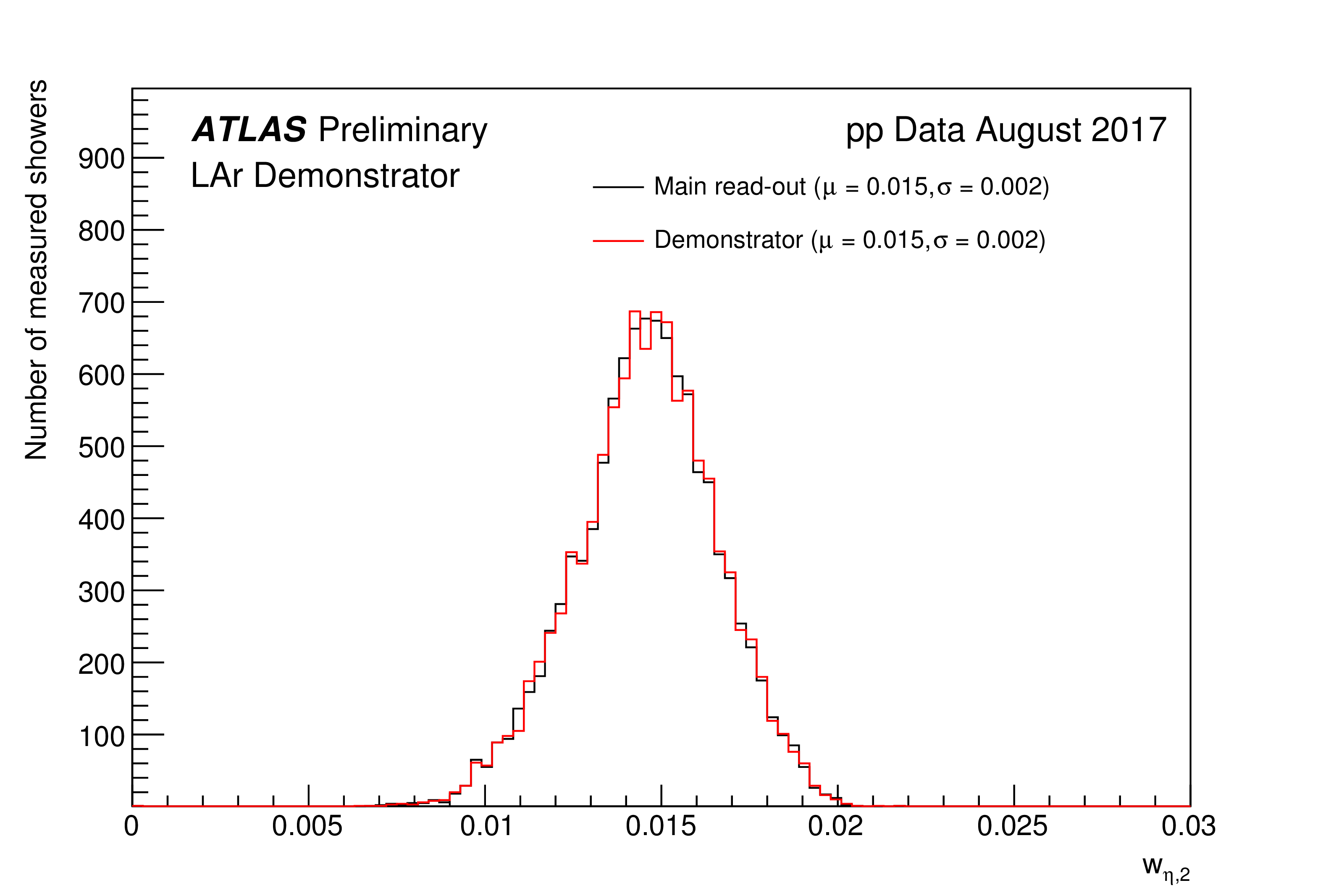
wη, 2 = ((Σ(E(2)T × η2)Δη×Δφ=0.075×0.2)/(E(2)T,Δη×Δφ=0.075×0.2) - ((Σ(E(2)T × η)Δη×Δφ=0.075×0.2)/(E(2)T,Δη×Δφ=0.075×0.2))2)0.5
f3 = (E(3)T,Δη×Δφ=0.2×0.2)/(E(1)T,Δη×Δφ=0.075×0.2 + E(2)T,Δη×Δφ=0.075×0.2 + E(3)T,Δη×Δφ=0.2×0.2)
| Measured energy comparison for the middle layer: The measured supercell (SC) energies of the LAr Phase I demonstrator are compared to summed LAr cell energies in ATLAS by calculating their ratio (ESC / ΣSC Ecells) for ESC > 2 GeV. The energy spectrum is subdivided into 15 bins and the width of the distribution shown. The supercells in the middle layer consist of 4 LAr cells. The width of the energy ratio is below 1 % in the high-energy tail. |
 eps version, pdf version |
||||||||||||
| Measured energy comparison by layer: The measured supercell (SC) energies of the LAr Phase I demonstrator are compared to summed LAr cell energies in ATLAS by calculating their ratio (ESC / ΣSC Ecells) for ESC > 2 GeV. The energy spectrum is subdivided into 15 bins and the width of the distribution shown. The supercells in the presampler, front, middle and back layer consist of 4, 8, 4 and 8 LAr cells, respectively. The width of the energy ratio is below 1 − 2 % in the high-energy tail, depending on the calorimeter layer. |
 eps version, pdf version |
||||||||||||
| Measured timing resolution for the middle layer: The measured supercell timing distribution of the LAr Phase I demonstrator is obtained for a selected supercell. It is subdivided into 15 energy-bins and the width of the distribution shown for each bin. The timing resolution is around 0.5 ns in the high-energy tail, such that the identification of the bunch-crossing ID is possible due to the resolution being much smaller than 25 ns. The supercells in the middle layer consist of 4 LAr cells. |
 eps version, pdf version |
||||||||||||
| Measured timing resolution by layer: The measured supercell timing distribution of the LAr Phase I demonstrator is obtained for selected supercells. It is subdivided into 15 energy-bins and the width of the distribution shown for each bin. The timing resolution is below 0.5 − 1.0 ns in the high-energy tail, such that the identification of the bunch-crossing ID is possible due to the resolution being much smaller than 25 ns. The supercells in the presampler, front, middle and back layer consist of 4, 8, 4 and 8 LAr cells, respectively. |
 eps version, pdf version |
||||||||||||
| Energy scale for demonstrator φ-slice: The measured supercell (SC) energies of the LAr Phase I demonstrator are compared to summed LAr cell energies in ATLAS by calculating their ratio (ESC / ΣSC Ecells) and the mean value of the distribution is shown. The supercells in the presampler, front, middle and back layer consist of 4, 8, 4 and 8 LAr cells, respectively. Good agreement is observed between the two systems, while residual shifts of the mean are due to the preliminary calibration of the supercells. |
 eps version, pdf version |
||||||||||||
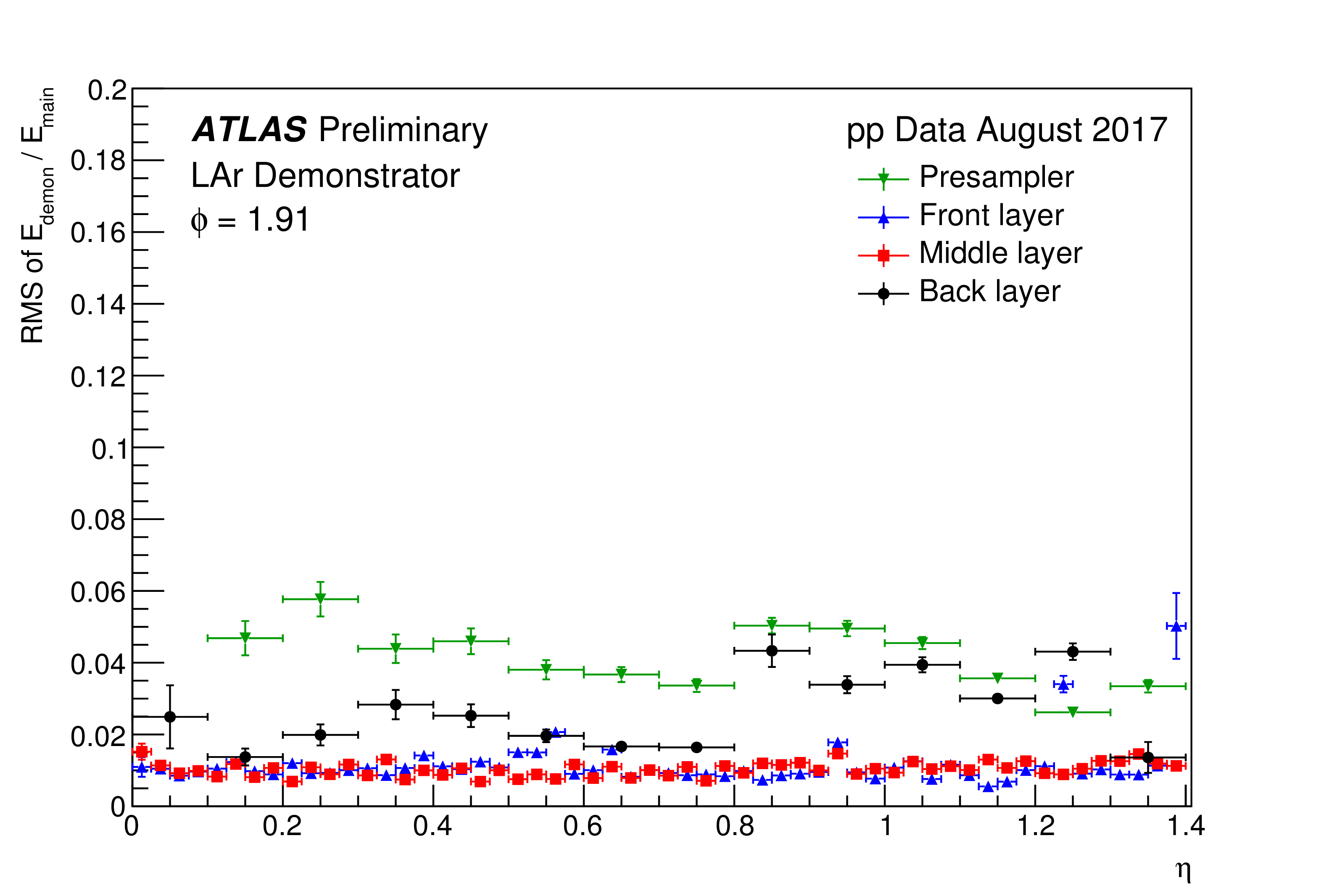
| Energy comparison for demonstrator φ-slice: The measured supercell (SC) energies of the LAr Phase I demonstrator are compared to summed LAr cell energies in ATLAS by calculating their ratio (ESC / ΣSC Ecells) and the RMS value of the distribution is shown. The supercells in the presampler, front, middle and back layer consist of 4, 8, 4 and 8 LAr cells, respectively. The typical width of the energy ratio of the front and middle layers is well below 2%, while the presampler and back layer exhibit higher values. |
 eps version, pdf version |
||||||||||||
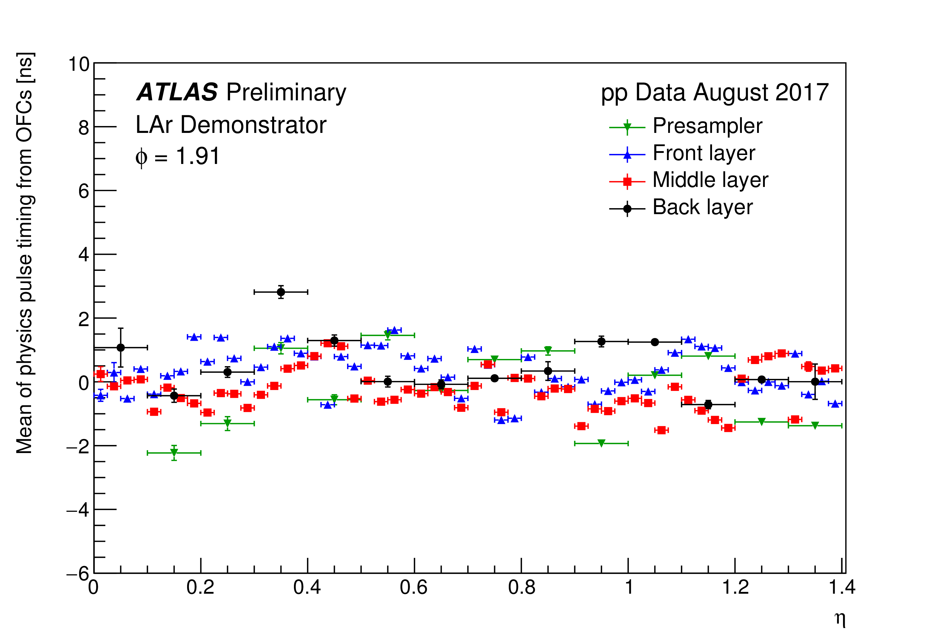
| Mean timing for demonstrator φ-slice: The measured supercell timing distribution of the LAr Phase I demonstrator is obtained and the mean value of the distribution shown. The identification of the bunch-crossing ID is possible due to the low deviation of the mean from 0 ns and a RMS value much smaller than 25 ns. The supercells in the presampler, front, middle and back layer consist of 4, 8, 4 and 8 LAr cells, respectively. The small shift of the means is due to the preliminary calibration of the supercells. |
 eps version, pdf version |
||||||||||||
| Timing resolution for demonstrator φ-slice: The measured supercell timing distribution of the LAr Phase I demonstrator is obtained and the RMS value of the distribution shown. The identification of the bunch-crossing ID is possible due to the low deviation of the mean from 0 ns and a RMS value much smaller than 25 ns. The supercells in the presampler, front, middle and back layer consist of 4, 8, 4 and 8 LAr cells, respectively. The typical timing resolution of the front and middle layers is below 1 ns, while the presampler and back layer have slight higher timing resolutions. |
 eps version, pdf version |
||||||||||||
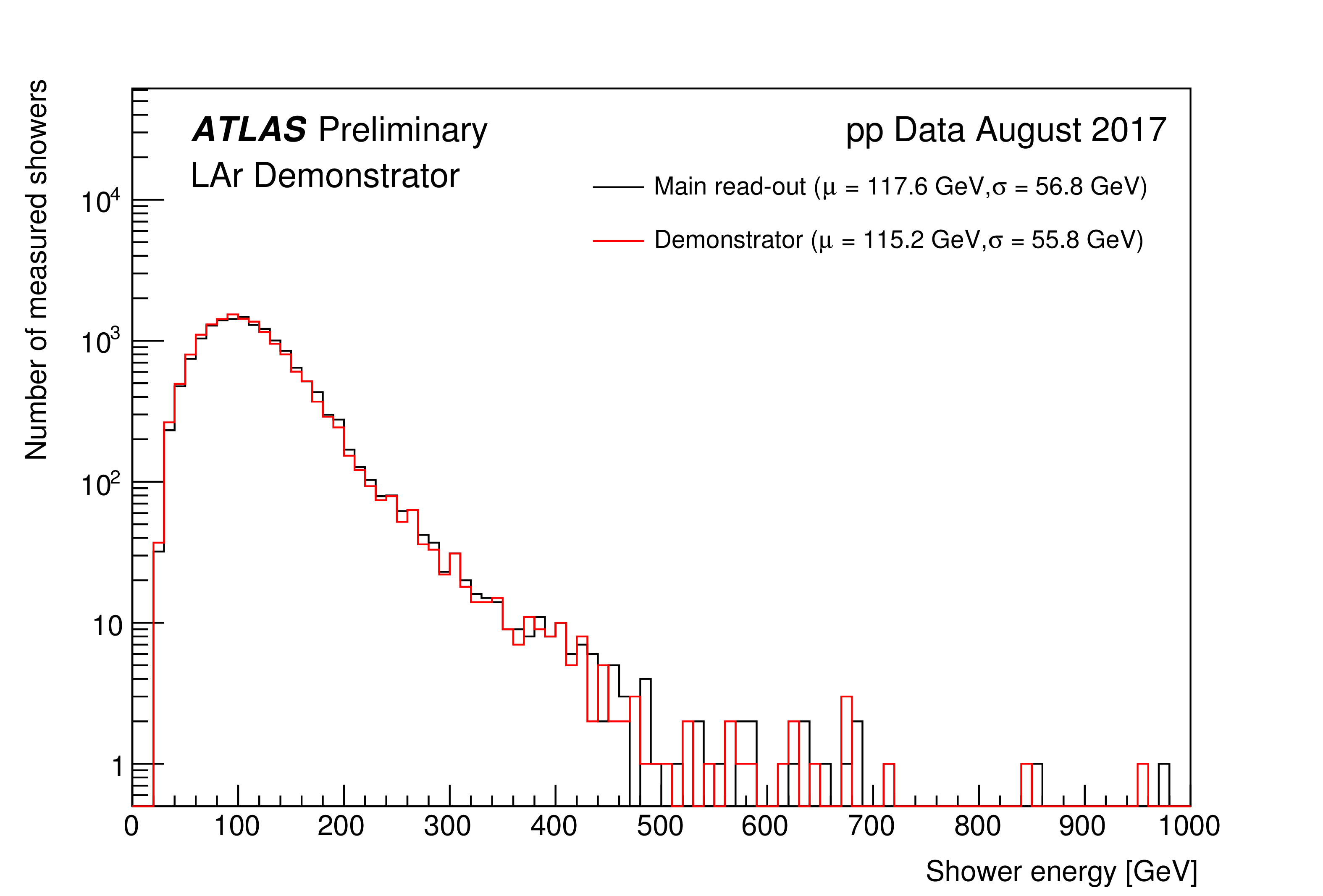
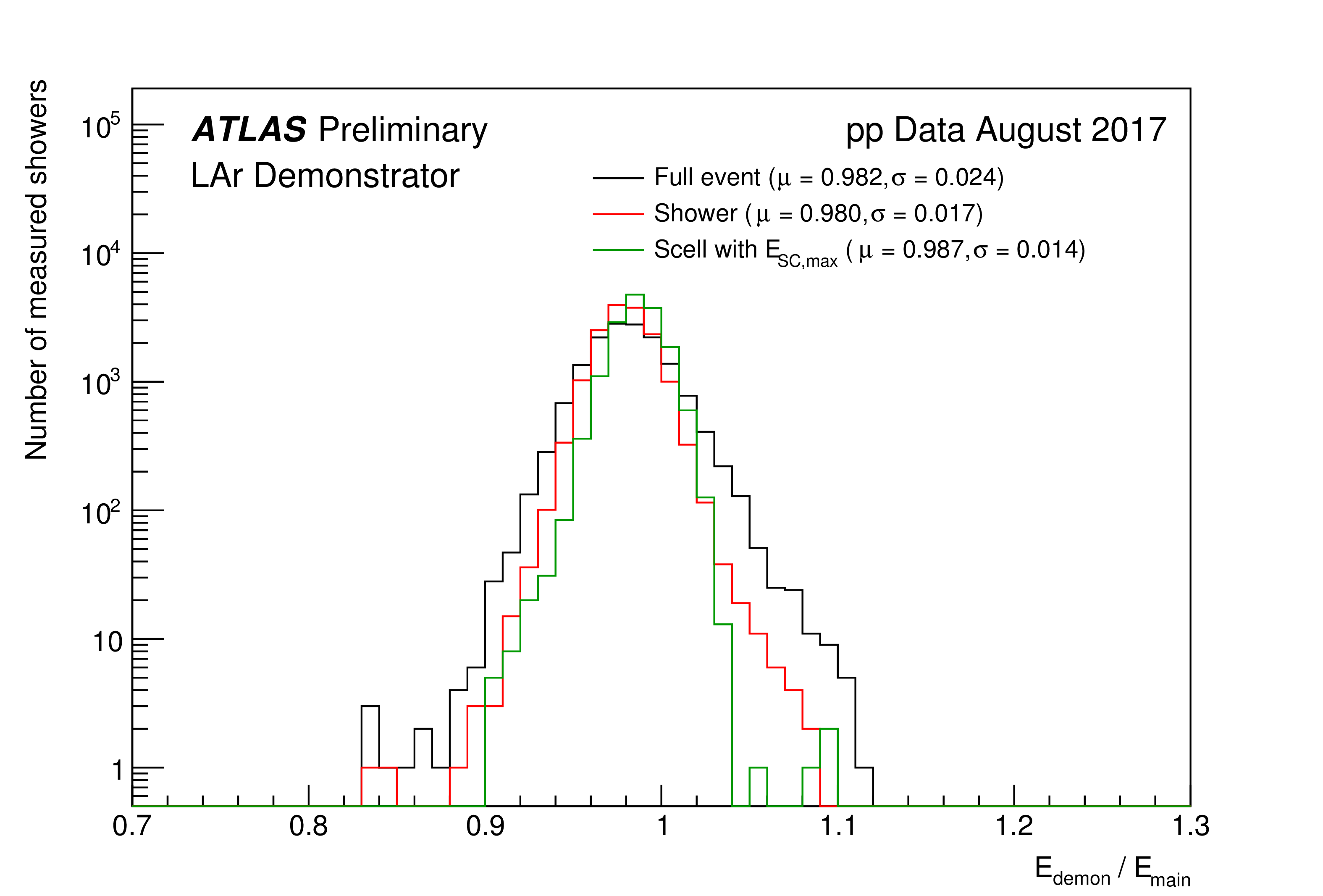
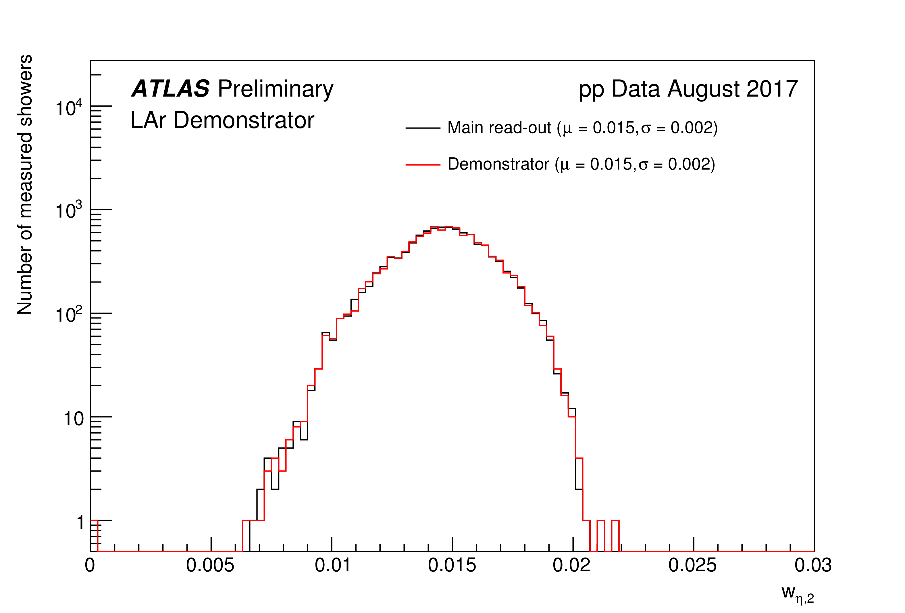
| Shower modelling of the demonstrator read-out: Supercell energy and timing information of the LAr Phase I demonstrator and summed LAr cell energies in ATLAS are compared for triggered showers. Several quantities are given and show a good agreement between the two read-outs. The events were observed in pp physics data, collected on August 30, 2017. Only well-reconstructed energy deposits above 1% of EmaxSC are used. Rη gives an estimate of the energy fraction of the shower cone in the middle layer, f3 is the energy fraction of the shower in the back layer and the width of the showers is further parametrised by wη, 2. |
|
Data from 2017 runs: pulse shapes and timing distributions
General Information- The plots show data from pp collisions, physics run 334487, recorded on August 30, 2017.
- Events were triggered by dedicated triggers requiring either a Level 1 electromagnetic cluster (EM) with ET > 20 GeV or a Level 1 Jet with ET > 100 GeV within the demonstrator acceptance (for EM (Jet) 1.6 < φ < 2.2 (2.3), 0 < η < 1.5). Those triggers were prescaled to have a combined event rate of approximately 1 Hz.
- Events from the LAr demonstrator are matched to events collected in the main read-out using their bunch-crossing ID and brunch-crossing time. An alternative method is the matching according to the L1 ID of the events.
- Measured pulse shapes for each layer and comparison with prediction:
- Measured pulse shapes are obtained from raw data of the demonstrator system and normalised according to measured energy in main read-out (to obtain a pulse height in ADC/GeV). Different options for averaging several events are applied.
- The Response Transformation Method is used to predict the pulse shape from calibration data. The normalisation is solely based on the dedicated demonstrator calibration coefficients and thus independent of the normalisation for the measured pulse shapes.
- Pulse timing distributions for each layer are based on the reconstruction of the demonstrator pulses with OFCs.
- Out of all events with |Edem − Emain |/Emain < 0.5 and Emain > 2 GeV, only the 20% highest energy deposits are used.
- cuts were checked to create no bias on pulse shape or timing
- cuts applied:
- Presampler: 4.70 GeV (178 events)
- Front layer: 7.80 GeV (133 events)
- Middle layer: 11.05 GeV (282 events)
- Back layer: 5.55 GeV (107 events)
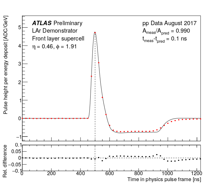
| Comparison of extracted pulse shapes for front layer: Measured pulse shapes (red) of a front layer supercell in the LAr Phase I demonstrator are compared to the, independently obtained, predicted pulse shape (black). The supercells in the presampler, front, middle and back layer consist of 4, 8, 4 and 8 LAr cells, respectively. Very good agreement between the different averaging methods is obtained. Only the five measurements around the peak (dashed line) are used for the energy and timing reconstruction. The shape difference at ≅ 1000 ns is expected to originate from the modeling of the electrode position in the LAr gap. |
 eps version, pdf version  eps version, pdf version  eps version, pdf version |
| Measured pulse shapes for each layer: Measured pulse shapes (red) of supercells in the LAr Phase I demonstrator are compared to the, independently obtained, predicted pulse shapes (black). The supercells in the presampler, front, middle and back layer consist of 4, 8, 4 and 8 LAr cells, respectively. Good agreement is observed between measurement and prediction, while remaining small normalisation offsets are due to the preliminary calibration of the supercells. Only the five measurements around the peak (dashed line) are used for the energy and timing reconstruction. The shape difference at ≅ 1000 ns is expected to originate from the modelling of the electrode position in the LAr gap. |
 eps version, pdf version  eps version, pdf version  eps version, pdf version 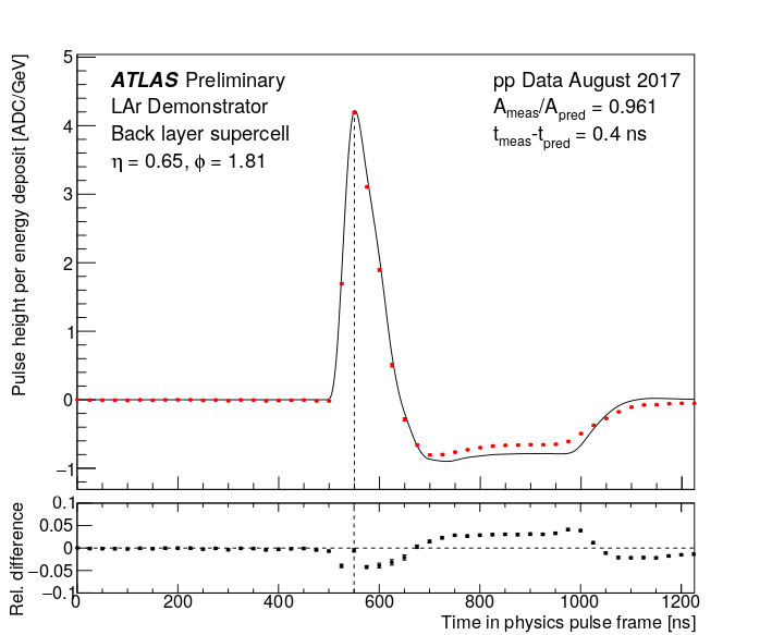 eps version, pdf version |
| Pulse timing distributions for each layer: The measured supercell timing distribution of the LAr Phase I demonstrator is given for selected supercells. The identification of the bunch-crossing ID is possible due to the low deviation of the mean from 0 ns and a RMS value much smaller than 25 ns. The supercells in the presampler, front, middle and back layer consist of 4, 8, 4 and 8 LAr cells, respectively. The average supercell energy of the used events is 6.7 GeV in the presampler, 13.3 GeV in the front layer, 24.2 GeV in the middle layer and 8.9 GeV in the back layer. The small shift of the means is due to the preliminary calibration of the supercells. |
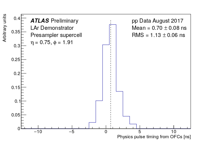 eps version, pdf version 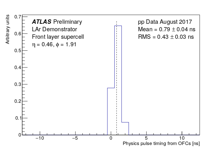 eps version, pdf version 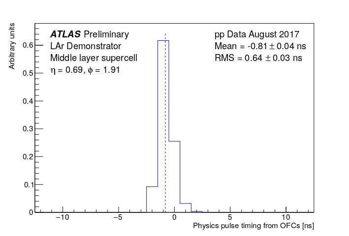 eps version, pdf version  eps version, pdf version |
Data from 2017 runs and event displays
- The plots show data from pp collisions, physics run 328099, recorded between June 27 and June 28, 2017.
- Events were triggered by dedicated triggers requiring either a Level 1 electromagnetic cluster (EM) with ET > 20 GeV or a Level 1 Jet with ET > 100 GeV within the demonstrator acceptance (for EM(Jet) 1.6 < φ < 2.2(2.3), 0 < η < 1.5). Those triggers were prescaled to have a combined event rate of approximately 1 Hz.
- Events from the LAr demonstrator are matched to events collected in the main read-out using their bunch-crossing ID and brunch-crossing time. An alternative method is the matching according to the L1 ID of the events.
| Correlation of energy measurements for each layer: The measured supercell (SC) energies of the LAr Phase I demonstrator are compared to summed LAr cell energies in ATLAS for ESC > 1 GeV. The supercells in the presampler, front, middle and back layer consist of 4, 8, 4 and 8 LAr cells, respectively. Good agreement is observed between the two read-outs. |
 eps version, pdf version  eps version, pdf version  eps version, pdf version 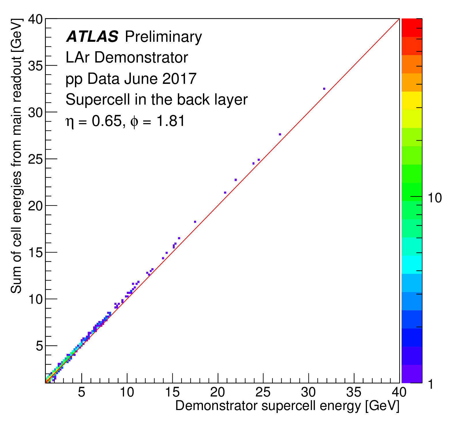 eps version, pdf version |
||||||||
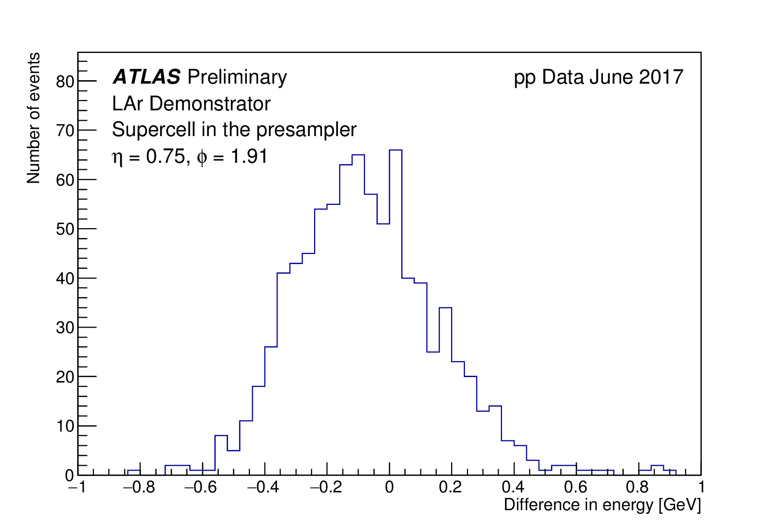
| Difference of energy measurements for each layer: The measured supercell (SC) energies of the LAr Phase I demonstrator are compared to summed LAr cell energies in ATLAS by calculating the difference (ESC − ΣSC Ecells) for ESC > 2 GeV. The supercells in the presampler, front, middle and back layer consist of 4, 8, 4 and 8 LAr cells, respectively. Good agreement is observed between the two read-outs. The width of the distribution is compatible with the expected noise level. The shift of the means is due to the preliminary calibration of the supercells. |
 eps version, pdf version  eps version, pdf version 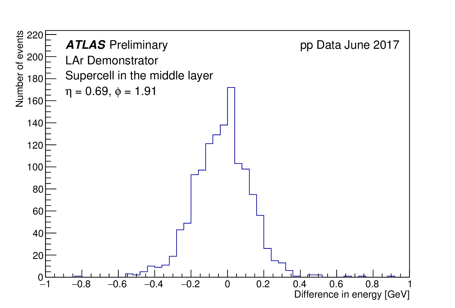 eps version, pdf version  eps version, pdf version |
||||||||
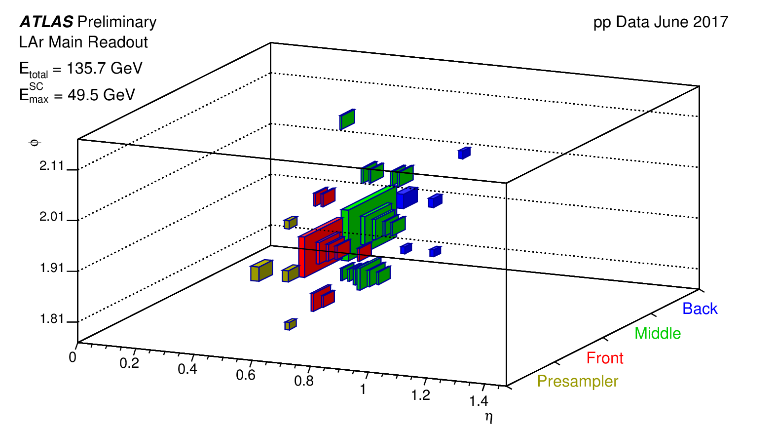
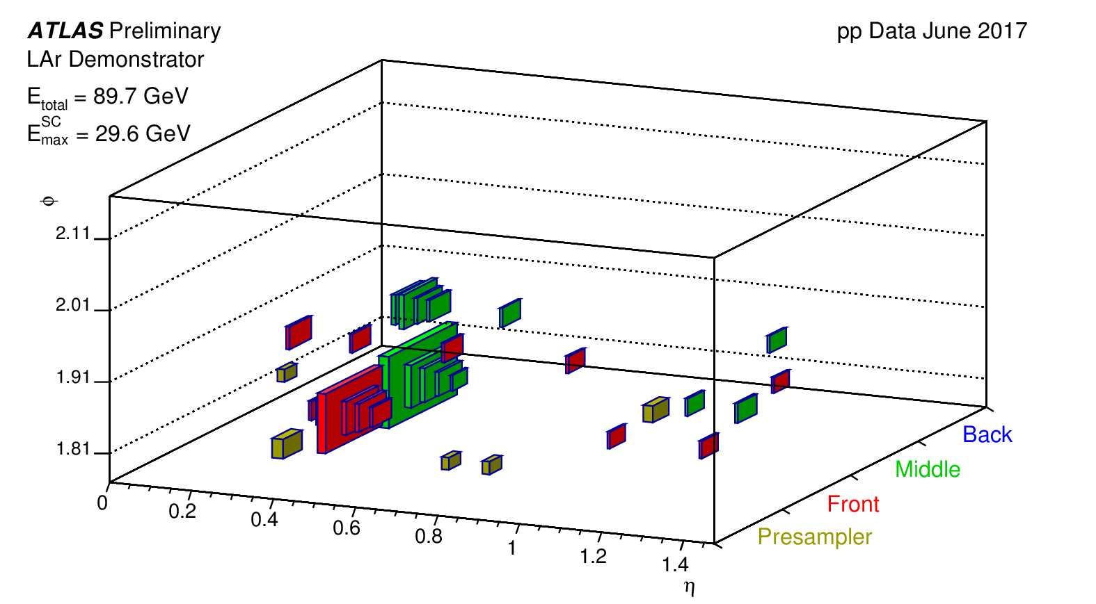
| Event display of the partial demonstrator region: Supercell energies of the LAr Phase I demonstrator and summed LAr cell energies in ATLAS are given for the same shower. The event with ID 1912797011 was observed in the pp physics run 328099, obtained between June 27 and June 28, 2017. The geometrical coverage of the demonstrator system is partially shown. The volume of the depicted boxes is proportional to the deposited energy. Only energy deposits above 1% of EmaxSC are plotted. |
|
||||||||
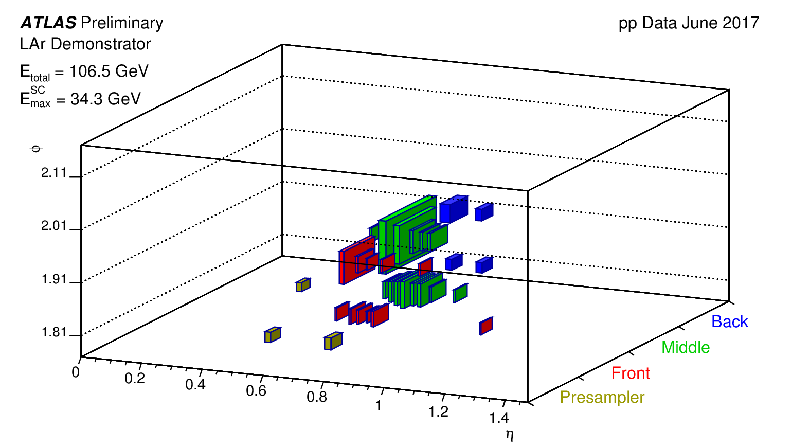
| Event display of the demonstrator region: Supercell energies of the LAr Phase I demonstrator and summed LAr cell energies in ATLAS are given for the same shower. The event with ID 2214598379 was observed in the pp physics run 328099, obtained between June 27 and June 28, 2017. The full geometrical coverage of the demonstrator system is shown. The volume of the depicted boxes is proportional to the deposited energy. Only energy deposits above 1% of EmaxSC are plotted. |
|
Noise and calibration pulse shapes
Noise values and calibration pulses with several amplitudes are shown in the following. Plots show ADC counts (12 bits ADC) as well as their equivalent transverse energies for the different sections of the calorimeter.| Super-cell pulse shapes for each layer: Responses of four super cells (one from each layer) from the LAr Phase I demonstrator installed in ATLAS to injected calibration pulses (DAC = 1000 counts to each LAr cell), the equivalent energy for DAC = 1000 is shown in subsequent plots. The super cell outputs are the sums of 4, 8, 4 and 8 LAr cells for Presampler, Front, Middle and Back layer, respectively. Size and shape of pulses are as expected and vary due to different detector and electronics properties. |

eps version, pdf version |
| Pulse maximum in ADC counts for each layer: Rapidity dependence of the pulse maximum in ADC counts (pedestal subtracted) for the super cells from the LAr Phase I demonstrator in ATLAS for injected calibration pulses (DAC = 1000 counts to each LAr cell), the equivalent energy for DAC = 1000 is shown in subsequent plots. The super cell outputs are the sums of 4, 8, 4 and 8 LAr cells for Presampler, Front, Middle and Back layer, respectively. The variations in response, especially in the back layer and at η = 0.8, are due to the change in electrode segmentation, calibration and readout electronics. |

eps version, pdf version |
| Equivalent transverse energy for each layer: Rapidity dependence of the equivalent transverse energy for an injected calibration pulse of DAC = 1000 counts into each LAr cell. The super cell outputs are the sums of 4, 8, 4 and 8 LAr cells for Presampler, Front, Middle and Back layer, respectively. The jump seen at η = 0.8 reflects the change of absorber thickness, electrodes and calibration resistors. |

eps version, pdf version |
| Noise level of super cells in ADC counts: Rapidity dependence of the noise (RMS) in ADC counts for the super cells from the LAr Phase I demonstrator in ATLAS. The super cell outputs are the sums of 4, 8, 4 and 8 LAr cells for Presampler, Front, Middle and Back layer, respectively. The jump seen at η = 0.8 reflects the change of electrodes’ segmentation at that position. The noise level is well below 1 ADC count and consistent with test bench measurements. |

eps version, pdf version |
| Noise level of super cells in transverse energy: Rapidity dependence of the noise (RMS) in transverse energy for the super cells from the LAr Phase I demonstrator in ATLAS. The super cell outputs are the sums of 4, 8, 4 and 8 LAr cells for Presampler, Front, Middle and Back layer, respectively. The jump seen at η = 0.8 reflects the change of absorber thickness, electrodes and calibration resistors. The noise level is as expected between 100 and 250 MeV per super cell. |

eps version, pdf version |
| Pulse shapes of a front layer super cell: Pulse shapes of a super cell from the LAr Phase I demonstrator installed in ATLAS for injected calibration pulses with different amplitudes (DAC = 2000, 4000, 6000, 8000, 10000 counts), the equivalent energy for these DAC values is shown in subsequent plots. The super cell outputs are the sums of 8 LAr front layer cells. Size and shape of pulses are as expected and show good linearity up to DAC = 8000, while beyond, analog saturation occurs upstream of the demonstrator board. |

eps version, pdf version |
| Pulse maximum versus DAC value: Pulse maximum (in ADC counts) for four different super cells from the LAr Phase I demonstrator installed in ATLAS for injected calibration pulses with different amplitudes (DAC = 2000, 4000, 6000, 8000, 10000 counts), the equivalent energies for these DAC values are shown in subsequent plots. The super-cell outputs are the sums of 8 (4) LAr front (middle) layer cells. Good linearity up to DAC = 8000 (DAC = 6000) for the front (middle) layer is observed, while beyond, analog saturation occurs upstream of the demonstrator board. |

eps version, pdf version |
| Pulse maximum versus transverse energy: Pulse maximum (in ADC counts) for four different super cells from the LAr Phase I demonstrator installed in ATLAS for injected calibration pulses with different amplitudes (DAC = 2000, 4000, 6000, 8000, 10000 counts), plotted in units of equivalent transverse energy. The super-cell outputs are the sums of 8 (4) LAr front (middle) layer cells. Analog saturation upstream of the demonstrator board occurs at different transverse energy values depending on the calorimeter layer and rapidity. |

eps version, pdf version |
| Total noise on the trigger readout path of the demonstrator test set-up: Here the RMS on the trigger readout path in MeV is shown. It was measured in a setup which is equivalent to a crate in ATLAS, with a half-full Front End Crate (FEC) equipped with Front End Boards (FEBs). Trigger towers 1-14 correspond to an eta-region of 0 to 1.4. Trigger towers 16-29 are the same in eta, but adjacent in phi. The values represented by the full circles were measured by a spectrum analyzer, the values shown in open circles were measured with Flash ADCs. For the computation a pedestal run with 5000 events and 8 samples was used. |

eps version |
| Fraction of total noise which is coherent for Phase I demonstrator measured in ATLAS: Here the total noise which is coherent is shown as fraction of the total noise per readout channel (Coherent Noise Fraction = CNF) The CNF for feedthroughs (FT) 7-12 on the detector has been computed, of which FT 9 and 10 belong to the demonstrator crate I06, FT 7 and 8 to I05 and FT 11 and 12 to I07. For the computation a pedestal run with 40000 events and 32 samples was used. The board in the first slot reads out the presampler, the boards in the following seven slots read out the front layer, the next two boards the back layer and the last four boards the middle layer of the calorimeter. The last entry is the CNF of the whole halfcrate. The coherent noise fraction rho was calculated using the formula in this link. |

eps version |
| LAr Trigger Digitizer Board (LTDB) demonstrator noise measured on the demonstrator installed in ATLAS: Here, the RMS of the 12-bit ADC of the 320 channels of the LTDB demonstrator measured in USA15 is shown. For the computation a pedestal run with 16384 events was used. One ADC count corresponds to roughly 125 MeV.. |

eps version |
| LAr Trigger Digitizer Board (LTDB) demonstrator pedestal measured on the demonstrator installed in ATLAS: Here, the pedestal values of the 12-bit ADC of the 320 channels of the LTDB demonstrator measured in USA15 are shown. For the computation a pedestal run with 16384 events was used. |

eps version |
| Total noise on main readout of calorimeter cells of demonstrator crate I06 (ATLAS): In this plot, the RMS of the 128 channels of the Front End Boards (FEBs) of the demonstrator crate installed in ATLAS is shown. The FEBs read out the calorimeter cells. There are 28 such boards in one Front End Crate (FEC). The FEBs read out signals from different layers of the calorimeter. The noise levels of the boards vary because different capacitances and gains are applied to their respective cells. For the computation of the RMS a pedestal run with 3000 events and 32 samples was used. The noise level is not higher compared to the neighboring crates on the detector (e.g. see plots for crate I05). |

eps version |
| Total noise on main readout of calorimeter cells of crate I05 (ATLAS): In this plot, the RMS of all channels of the FEBs of one of the neighbour crates (I05) of the demonstrator crate I06 in ATLAS is shown. For the computation of the noise a pedestal run with 3000 events and 32 samples was used. |

eps version |
Phase II Upgrade Plots
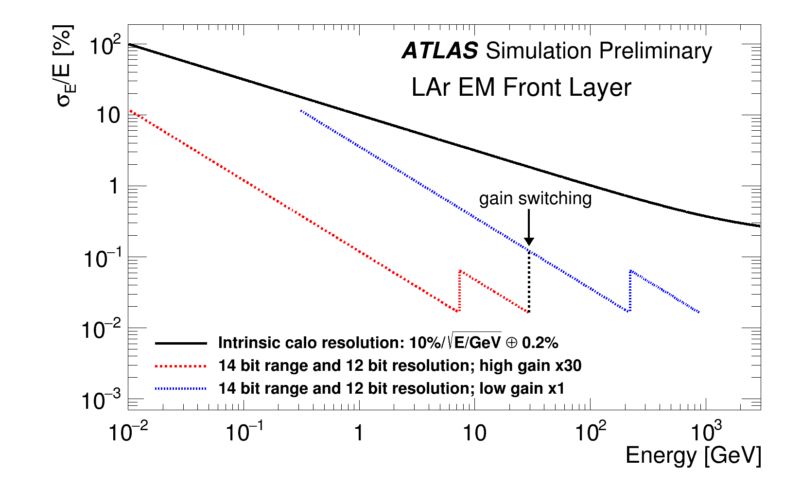
| Estimated quantization noise as function of energy in the front layer of the LAr EM barrel calorimeter, with the two gain system proposed for the Phase-II LAr Calorimeter readout (low gain curve in red, high gain curve in blue). The quantization noise curves assume the use of a 12-bit successive approximation register (SAR) with a dynamic range enhancer (DRE) to obtain a 14-bit ADC with 12-bit precision. Gain switching occurs close to the highest energy digitized in the high gain. |
 eps version, pdf version |
| Estimated quantization noise as function of energy in the LAr EM middle layer in the endcap outer wheel, with the two gain system proposed for the Phase-II LAr Calorimeter readout (low gain curve in red, high gain curve in blue). The quantization noise curves assume the use of a 12-bit successive approximation register (SAR) with a dynamic range enhancer (DRE) to obtain a 14-bit ADC with 12-bit precision. Gain switching occurs close to the highest energy digitized in the high gain. |
 eps version, pdf version |
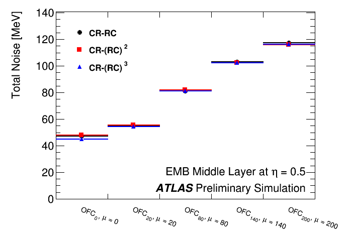
| Bipolar shapers can have different numbers of integration stages, as well as various peaking times, which both affect the total noise (electronics plus pileup) on the analog pulse of the Phase-II LAr Calorimeter readout. The figure shows the total noise as a function of the level of pileup, μ, for a cell from the EM middle layer at η = 0.5, obtained after optimal filtering, for different number of integration stages in the shaper. The optimal filtering coefficients (OFC) are computed for each case separately. No significant differences in the noise level can be seen in the EM case. These results do not include a detailed simulation of the electronics circuit, which could affect the results. |
 eps version, pdf version |
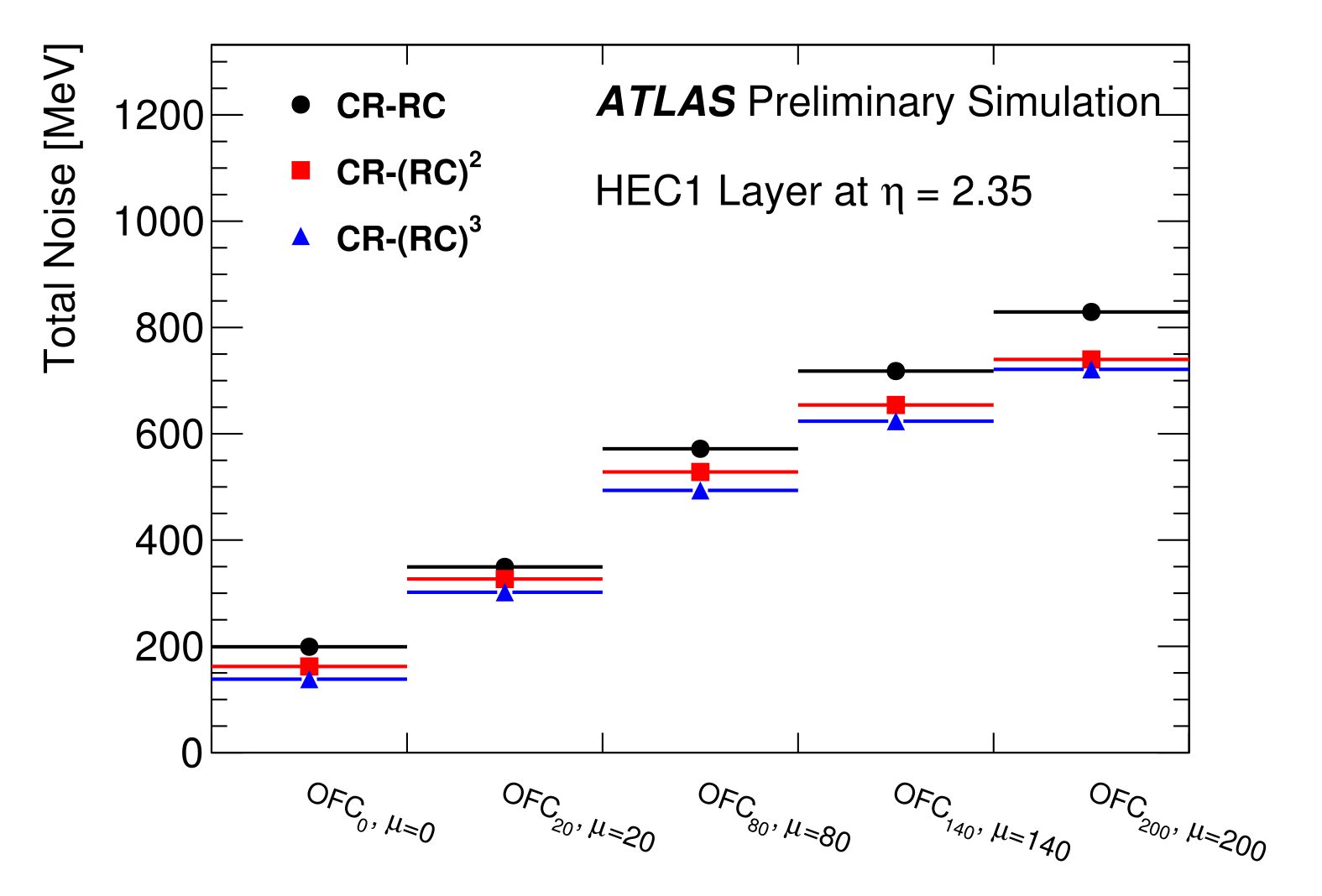
| Bipolar shapers can have different numbers of integration stages, as well as various peaking times, which both affect the total noise (electronics plus pileup) on the analog pulse of the Phase-II LAr Calorimeter readout. The figure shows the total noise as a function of the level of pileup, μ, for a HEC cell in the first layer at η = 2.35, obtained after optimal filtering, for different number of integration stages in the shaper. The optimal filtering coefficients (OFC) are computed for each case separately. For the HEC, a CR-(RC)3 shaper improves the noise by 5% over a CR-(RC)2. These results do not include a detailed simulation of the electronics circuit, which could affect the results. |
 eps version, pdf version |
NIEL Simulations for HEC Cold Electronics in Phase II
| Si NIEL fluence in ATLAS under HL-LHC conditions after 3000 fb-1 and with an applied safety factor of 2 to account for simulation uncertainties. The color coded fluences in the ASICs are shown at the r-z locations of the corresponding readout regions of the HEC. |

eps version, pdf version |
| Si NIEL fluence in ATLAS under HL-LHC conditions after 3000 fb-1 and with an applied safety factor of 2 to account for simulation uncertainties. The color coded fluences in the ASICs are shown at the r-z locations of the corresponding readout regions of the HEC. |

eps version, pdf version |
Simulated Noise
|
Simulated noise in the Liquid Argon and Tile calorimeters at the electron scale (bunch spacing |
 Total noise for L=1.09x1034 corresponding to <µ>=30 eps version  Total noise for L=1.45x1034 corresponding to <µ>=40 eps version  Total noise for L=2.17x1034 corresponding to <µ>=60 eps version  Total noise for L=2.90x1034 corresponding to <µ>=80 eps version  Total noise for L=3.62x1034 corresponding to <µ>=100 eps version  Total noise for L=5.07x1034 corresponding to <µ>=140 eps version  Total noise for L=7.25x1034 corresponding to <µ>=200 eps version |
|
Simulated noise in the Liquid Argon and Tile calorimeters at the electron scale (bunch spacing |
 Total noise for L=0.54x1034 corresponding to <µ>=30 eps version  Total noise for L=0.73x1034 corresponding to <µ>=40 eps version  Total noise for L=1.09x1034 corresponding to <µ>=60 eps version  Total noise for L=1.45x1034 corresponding to <µ>=80 eps version  Total noise for L=1.81x1034 corresponding to <µ>=100 eps version  Total noise for L=2.54x1034 corresponding to <µ>=140 eps version  Total noise for L=3.62x1034 corresponding to <µ>=200 eps version |
High Granularity FCal Performance Studies
The below results are based on simulated VBF 2.6 TeV Higgs boson production and di-jet production at 14 TeV with μ=190-200 assuming the current ATLAS FCal, a high-granularity sFCal and the FCal with reduced acceptance| Total Noise Ratio: Noise ratio per calorimeter cell as a function of |η| for all layers for a high- granularity sFCal over FCal at a centre-of-mass energy of 14 TeV and for a mean number of pile-up event of μ=200. Small deviations from 1 in the inner-most (s)FCal1 and full (s)FCal2/3 layers are due to the 6% denser sFCal1 compared to FCal1 which causes inelastic pp collisions to deposit more energy in the first module. In the outer region of sFCal1 the noise is 0.4 times the FCal1 noise. The ratio 1.1/0.4 = 2.75 of ratios for inner over outer cells is non-trivial and indicates that an sFCal with finer granularity improves the separation of hard-scatter signal from pile-up. The granularity ratio is 4. Therefore a double ratio of 4 would mean no improvement at all since all small cells would be fully correlated. A double ratio of 2 would be the maximal possible improvement in case all small cells are uncorrelated. 2.75 lies between these extremes, and since it is smaller than 4 means that the increase in granularity helps to suppress pile-up. |

eps version, pdf version |
| Number of Jet Constituents: Distribution of the number of constituents (clusters) for quark jets produced in the vector-boson fusion process 𝑝𝑝 → 𝐻 𝑞𝑞 → 𝑙−𝑣 𝑙+𝑣 𝑞𝑞 at 14 TeV centre-of-mass energy simulated for the current ATLAS FCal, a high-granularity sFCal, and three scenarios with reduced FCal acceptance. The increase in granularity and better separation of signal from pile-up leads to larger number of constituents in the sFCal compared to FCal. The vector-boson fusion events were simulated with the Powheg and Pythia8 Monte Carlo generators in narrow-width approximation for a hypothetic Higgs boson mass of 2.6 TeV and an average number of pile-up events, μ, between 190 and 210. |

eps version, pdf version |
| Cell Significance: Cell significance (Ecell/σcell) for the cell with the largest absolute cell energy over total noise simulated for the current ATLAS FCal, a high-granularity sFCal, and three scenarios with reduced FCal acceptance. Clusters are seeded when the absolute ratio is above 4. Cluster splitting can lead to entries with smaller ratios. The sFCal distribution is enhanced on the positve side while it remains close to the FCal distribution on the negative side. The negative entries are due to pile-up only, while on the positve side signal and pile- up contribute. The increase of mainly the positive side indicates that the signal detection ability is improved for the sFCal while the background remains on the same level. The distributions are obtained for vector-boson fusion events 𝑝𝑝 → 𝐻 𝑞𝑞 → 𝑙−𝑣 𝑙+𝑣 𝑞𝑞 at 14 TeV centre-of-mass energy, simulated with the Powheg and Pythia8 Monte Carlo generators in narrow-width approximation for a hypothetic Higgs boson mass of 2.6 TeV and an average number of pile-up events, μ, between 190 and 210. |

eps version, pdf version |
| Average pT Density: Shown is the simulated profile of the average median pT density, ρ, evaluated from positive-energy cell towers in the ATLAS LAr calorimeters. For the forward calorimeter, five different scenarios are studied: the current ATLAS FCal, a high-granularity sFCal, and three scenarios with reduced FCal acceptance. When a ρ-based pile-up suppression will be applied in the jet reconstruction it is expected that a larger amount of pT will be removed for jets in the forward region in case of the sFCal. The distributions are obtained for vector-boson fusion events 𝑝𝑝 → 𝐻 𝑞𝑞 → 𝑙−𝑣 𝑙+𝑣 𝑞𝑞 at 14 TeV centre-of-mass energy, simulated with the Powheg and Pythia8 Monte Carlo generators in narrow-width approximation for a hypothetic Higgs boson mass of 2.6 TeV and an average number of pile-up events, μ, between 190 and 210. |

eps version, pdf version |
| Number of Jets: Simulated integral jet pT distribution for hard scattering and pile-up jets and the relative fraction of hard scattering jets detected in the ATLAS FCal and in a high-granularity sFCal. An area-based pT subtraction is applied. The amount of pT subtracted from a jet is increased by a factor of 10 (thereby effectively killing the jet) in the case that it fails one of the jet shape variable cuts, which are based on jet width, transverse momentum sum of the jet constituents relative to the jet direction and the electromagnetic energy fraction. The distributions are obtained for vector-boson fusion events 𝑝𝑝 → 𝐻 𝑞𝑞 → 𝑙−𝑣 𝑙+𝑣 𝑞𝑞 at 14 TeV centre-of-mass energy, simulated with the Powheg and Pythia8 Monte Carlo generators in narrow-width approximation for a hypothetic Higgs boson mass of 2.6 TeV and an average number of pile-up events, μ, between 190 and 210. |

eps version, pdf version |
| Ratio of Pile-Up Jets: Ratio of number of identified pile-up jets and total number of reconstructed jets as a function of efficiency for determining a hard-scattering jet as simulated in di-jet events at 14 TeV for the ATLAS FCal and a high-granularity sFCal. All jets are selected in the pseudo-rapidity range 3.8<|η|<4.2 and in the pT range between 50 GeV and 70 GeV. Also shown is the double- ratio comparing the sFCal and FCal performance. The jet classification was performed using a likelihood ratio constructed from the jet width, the jet mass, the transverse momentum sum of the jet constituents relative to the jet direction, and the number of jet constituents (clusters). |

eps version, pdf version |
| Number of Pile-Up Jets: Number of identified pile-up jets per event as a function of efficiency for determining a hard-scattering jet in high-mass VBF Higgs events at 14 TeV for the ATLAS FCal and a high- granularity sFCal. All jets are selected in the pseudo-rapidity range 3.2<|η|<3.8 and in the pT range above 20 GeV. The jet reconstruction requires a positive cluster-vertex-fraction and a pile- up correction based on the average median pT density, ρ, evaluated from positive-energy cell towers in the ATLAS LAr calorimeters. The simulation of charged particle tracks is based on the ITk tracking system assuming a tracking coverage of |η|<4 and an ideal ITk detector resolution. The distributions are obtained for vector-boson fusion events 𝑝𝑝 → 𝐻 𝑞𝑞 → 𝑙−𝑣 𝑙+𝑣 𝑞𝑞 at 14 TeV centre-of-mass energy, simulated with the Powheg and Pythia8 Monte Carlo generators in narrow-width approximation for a hypothetic Higgs boson mass of 2.6 TeV and an average number of pile-up events, μ, between 190 and 210. |

eps version, pdf version |
LAr Phase-II Energy Reconstruction with Artificial Neural Networks and Implementation in FPGAs
The results below are based on simulated energy deposits in the LAr EMB at a mean number of pile-up events of <μ>=140. The simulation of the sample sequences have been prepared using the AREUS software. The neural network development has been performed using the Keras/Tensorflow frameworks. FPGA implementations are for an Intel Stratix-10.|
Top: Sample sequence (black) of an EMB Middle cell at (η,φ)=(0.5125,0.0125) as simulated by AREUS, together with the true transverse energy deposits (yellow) shifted by five BC to improve the plot visibility, at <μ>=140 as a function of the BC counter. Middle: The Convolutional Neural Network (CNN) for pulse tagging provides a hit probability (green) for each BC. Its training is based on a binary input sequence (blue) with values of unity for energy deposits 3 σ above noise threshold. Bottom: The transverse energy reconstruction CNN makes its predictions (green) based on the probability of the tagging layer and the input samples. |

eps version, pdf version |
| Architecture of an Artificial Neural Network (ANN) with four convolutional layers. The dataflow goes from bottom to top. The input sequence is first processed by the tagging part of the network in the bottom part of the figure. After a concatenation layer, the tag output and the input sequence are processed by the transverse energy reconstruction part of the ANN. The total receptive field of this network incorporates 13 bunch crossings. |

eps version, pdf version |
| Signal efficiency and background rejection receiver operating characteristic (ROC) curves of the two presented Artificial Neural Networks (yellow, purple) and their tagging part (green), compared to the Optimal Filtering (OF) with MaxFinder (red). Signal refers to deposits with ETtrue above 240 MeV (3σ above noise threshold), background those below. Efficiencies are calculated for an EMB Middle LAr cell (η=0.5125 and φ=0.0125) simulated with AREUS assuming <μ>=140. Approaching the upper right corner of the plot indicates signal efficiencies of 100% and a background rejection of 100% and would therefore be optimal. For better visibility, the results are shown only in the range above 75%. Filled bands represent the statistical uncertainty. |

eps version, pdf version |
| Single-cell application of Long Short-Term Memory (LSTM) based recurrent networks. The LSTM cell and its dense decoder are computed at every bunch crossing (BC). They analyse the present signal amplitude and output of the past cell, accumulating long range information through a recurrent application. By design, the network predicts the deposited transverse energy with a delay of six BC. |

eps version, pdf version |
| Sliding window application of LSTM based recurrent networks. At each instant, the signal amplitude of the four past and present bunch crossings are input into an LSTM layer. The last cell output is concatenated with a dense operation consisting of a single neuron, and providing the transverse energy prediction. |

eps version, pdf version |
| Transverse energy reconstruction performance for the optimal filtering and the various ANN algorithms. The performance is assessed by comparing the true transverse energy deposited in an EMB Middle LAr cell (η=0.5125 and φ=0.0125) to the ANN prediction after simulating the sampled pulse with AREUS assuming <μ>=140. Only energies 3σ above the noise threshold are considered. The mean, the median, the standard deviation, and the smallest range that contains 98% of the events are shown. |

eps version, pdf version |
| Resolution of the transverse energy reconstruction as a function of the gap, i.e. the distance in units of bunch crossings (BC), between two consecutive energy deposits for the optimal filtering (OF) algorithm and a subsequent maximum finder. Only deposits with ETtrue above 240 MeV (3σ above noise threshold) are considered. Inputs to the OF are sampled pulses obtained from the simulation of an EMB Middle LAr cell (η=0.5125 and φ=0.0125) with AREUS using <μ>=140. |

eps version, pdf version |
| Resolution of the transverse energy reconstruction as a function of the gap, i.e. the distance in units of bunch crossings (BC), between two consecutive energy deposits for the Long Short-Term Memory single-cell algorithm. Only deposits with ETtrue above 240 MeV (3σ above noise threshold) are considered. Inputs to the LSTM are sampled pulses obtained from the simulation of an EMB Middle LAr cell (η=0.5125 and φ=0.0125) with AREUS using <μ>=140. |

eps version, pdf version |
| Resolution of the transverse energy reconstruction as a function of the gap, i.e. the distance in units of bunch crossings (BC), between two consecutive energy deposits for the Vanilla-RNN sliding-window algorithm. Only deposits with ETtrue above 240 MeV (3σ above noise threshold) are considered. Inputs to the Vanilla-RNN are sampled pulses obtained from the simulation of an EMB Middle LAr cell (η=0.5125 and φ=0.0125) with AREUS using <μ>=140. |

eps version, pdf version |
| Resolution of the transverse energy reconstruction as a function of the gap, i.e. the distance in units of bunch crossings (BC), between two consecutive energy deposits for the Convolutional Neural Network (CNN) algorithm. Only deposits with ETtrue above 240 MeV (3σ above noise threshold) are considered. Inputs to the CNN are sampled pulses obtained from the simulation of an EMB Middle LAr cell (η=0.5125 and φ=0.0125) with AREUS using <μ>=140. |

eps version, pdf version |
| Relative deviation of the firmware implementations from the software results for the different transverse energy reconstruction Artificial Neural Networks (ANN). Only bunch crossings with predictions different from zero and true transverse energies larger than 240 MeV are considered. Inputs to the ANNs are sampled pulses obtained from the simulation of an EMB Middle LAr cell (η=0.5125$ and &ph;i=0.0125) with AREUS assuming <μ>=140. |

eps version, pdf version |
| Architecture of an Artificial Neural Network (ANN) with four convolutional layers and tagging part. The data flow goes from bottom to top. The input sequence is first processed by the tagging part of the network in the bottom half of the figure. After a concatenation layer, the tag output and the input sequence are processed by the transverse momentum magnitude reconstruction part of the ANN. The total field of view of this network incorporates 20 bunch crossings. |

eps version, pdf version |
| Architecture of an Artificial Neural Network (ANN) with two convolutional layers. The data flow goes from bottom to top. The input sequence is first processed by a convolutional layer with dilation 1, which densely screens its input samples. The second convolutional layer with dilation 3 sparsely screens the output of the previous layer. This results in a larger total field of view of 22 bunch crossings without increasing the number of parameters. |

eps version, pdf version |
|
Top: Display of a sample sequence (black) of an EMB Middle cell at (η,φ)=(0.5125,0.0125), together with the true transverse momentum magnitude ET (blue) and the Optimal Filtering (OF) with MaxFinder output (red) as a function of the BC counter.
Bottom: Similar display but with the output of the 2-Conv Convolutional Neural Network (CNN) (red). The sequence was simulated with AREUS, using <μ>=140. True energies include in-time pile-up. The CNN shows an improvement in detecting hits coming in close succession. The two hits with a gap of 2 around bunch crossing 5 are well reconstructed by the CNN. That is not the case for the OF, which detects only a single peak. Around BC 65 a hit follows within an undershoot of a previous hit. While the OF underestimates its energy, the CNN reconstructs it much better. |

eps version, pdf version |
| Difference of the reconstructed and true transverse momentum magnitude (ET) as a function of the gap, i.e. the distance in units of bunch crossings (BC), between two consecutive energy deposits for the 4-Conv with Tagging Convolutional Neural Network (CNN) algorithm. Inputs to the CNN are sampled pulses obtained from the simulation of an EMB Middle LAr cell (η=0.5125 and φ=0.0125) with AREUS using <μ>=140. The structure at ETpred-ETtrue=-0.5 GeV arises, since only deposits with ETtrue (including in-time pile-up) above 0.5 GeV are considered. |

eps version, pdf version |
| Difference of the reconstructed and true transverse momentum magnitude (ET) as a function of the gap, i.e. the distance in units of bunch crossings (BC), between two consecutive energy deposits for the 2-Conv Convolutional Neural Network (CNN) algorithm for a set of representative detector cells. Inputs to the CNN are sampled pulses obtained from the AREUS simulation using <μ>=140. The structure at ETpred-ETtrue=-0.5 GeV arises, since only deposits with ETtrue (including in-time pile-up) above 0.5 GeV are considered. |

eps version, pdf version 
eps version, pdf version 
eps version, pdf version 
eps version, pdf version 
eps version, pdf version 
eps version, pdf version |
| Difference of the reconstructed and true transverse momentum magnitude (ET) as a function of the gap, i.e. the distance in units of bunch crossings (BC), between two consecutive energy deposits for the Optimal Filtering (OF) algorithm and a subsequent MaxFinder. Inputs to the OF are sampled pulses obtained from the simulation of an EMB Middle LAr cell (η=0.5125 and φ=0.0125) with AREUS using <μ>=140. The structure at ETpred-ETtrue=-0.5 GeV arises, since only deposits with ETtrue (including in-time pile-up) above 0.5 GeV are considered. |

eps version, pdf version |
|
Distribution of the deviation between predicted and true transverse momentum magnitude (ET) for the Optimal Filtering Algorithm (OF) with MaxFinder (red), a four-layered Convolutional Neural Network with tagging part (orange) and a plain two-layered Convolutional Neural Network (blue). The histogram content is normalized to the number of total entries within the displayed axis range. Inputs to the filters are sampled pulses obtained from the simulation of an EMB Middle LAr cell (η=0.5125 and φ=0.0125) with AREUS using <μ>=140. Artificial signal hits following a flat energy distribution up to 130 GeV with a gaussian distributed distance (μ=30, σ=10 BC) are injected. Top: Only signals with ETtrue lower than 0.5 GeV contribute. Middle: Only signals with ETtrue larger than 0.5 GeV contribute. Bottom: Median with 68 % range and gaussian fitted mean with standard deviation for bins of ETtrue. |

eps version, pdf version 
eps version, pdf version 
eps version, pdf version |
| Spectrum of transverse momentum magnitude (ET) predictions for the two presented Artificial Neural Networks (orange, blue), compared to the Optimal Filter (OF) with MaxFinder, for bunch crossings without any energy deposit. ETtrue includes in-time pile-up. The evaluation data stream was simulated for an EMB Middle LAr cell (η=0.5125 and φ=0.0125) with AREUS using <μ>=140. |

eps version, pdf version |
Major updates:
-- MartinAleksa - 06-Aug-2013 Responsible: MartinAleksa
Subject: public
Local page variables
This section contains local page variables that you can use in editing this page to avoid hardcoding long paths etc. To use the variable, just enclose it with %, like: %IMG{name}% which will turn into- Set IMGNAME = %IF{"attachments[name='%DEFAULT{default="fig1"}%.png']" then="%DEFAULT{default="fig1"}%.png" else="%IF{"attachments[name='%DEFAULT{default="fig1"}%.jpg']" then="%DEFAULT{default="fig1"}%.jpg" else="%IF{"attachments[name='%DEFAULT{default="fig1"}%.jpeg']" then="%DEFAULT{default="fig1"}%.jpeg" else="File '%DEFAULT{default="fig1"}%' not found!"}%"}%"}%
- Set IMGPATH = /twiki/pub/AtlasPublic/LArCaloPublicResultsUpgrade/%IMGNAME{%DEFAULT{default="fig1"}%}%
- Set IMG =
- Set PDF = pdf version
- Set EPS = eps version
- Set PLOT = %IMG{%DEFAULT{default="fig1"}%}%
%EPS{%DEFAULT{default="fig1"}%}%, %PDF{%DEFAULT{default="fig1"}%}% - Set HALFPLOT = %IMG{"%DEFAULT{default="fig1"}%" IMGSIZE="175"}%
%EPS{%DEFAULT{default="fig1"}%}%, %PDF{%DEFAULT{default="fig1"}%}%
| I | Attachment | History | Action | Size | Date | Who | Comment |
|---|---|---|---|---|---|---|---|
| |
Event_0_Demonstrator_Full.eps | r1 | manage | 21.7 K | 2017-09-12 - 14:03 | SteffenStaerz | Demonstrator event display: event 0 (full) |
| |
Event_0_Demonstrator_Full.pdf | r1 | manage | 17.1 K | 2017-09-12 - 14:03 | SteffenStaerz | Demonstrator event display: event 0 (full) |
| |
Event_0_Demonstrator_Full.png | r2 r1 | manage | 96.2 K | 2017-09-12 - 14:47 | SteffenStaerz | Demonstrator event display: event 0 (full) |
| |
Event_0_Demonstrator_Partial.eps | r1 | manage | 20.3 K | 2017-09-12 - 14:04 | SteffenStaerz | Demonstrator event display: event 0 (zoom) |
| |
Event_0_Demonstrator_Partial.pdf | r1 | manage | 16.6 K | 2017-09-12 - 14:04 | SteffenStaerz | Demonstrator event display: event 0 (zoom) |
| |
Event_0_Demonstrator_Partial.png | r3 r2 r1 | manage | 102.3 K | 2017-09-12 - 14:48 | SteffenStaerz | Demonstrator event display: event 0 (zoom) |
| |
Event_0_Main_Full.eps | r1 | manage | 22.8 K | 2017-09-12 - 14:03 | SteffenStaerz | Demonstrator event display: event 0 (full) |
| |
Event_0_Main_Full.pdf | r1 | manage | 17.4 K | 2017-09-12 - 14:03 | SteffenStaerz | Demonstrator event display: event 0 (full) |
| |
Event_0_Main_Full.png | r2 r1 | manage | 98.4 K | 2017-09-12 - 14:49 | SteffenStaerz | Demonstrator event display: event 0 (full) |
| |
Event_0_Main_Partial.eps | r1 | manage | 23.6 K | 2017-09-12 - 14:04 | SteffenStaerz | Demonstrator event display: event 0 (zoom) |
| |
Event_0_Main_Partial.pdf | r1 | manage | 17.7 K | 2017-09-12 - 14:04 | SteffenStaerz | Demonstrator event display: event 0 (zoom) |
| |
Event_0_Main_Partial.png | r3 r2 r1 | manage | 110.3 K | 2017-09-12 - 14:50 | SteffenStaerz | Demonstrator event display: event 0 (zoom) |
| |
Event_1_Demonstrator.eps | r1 | manage | 22.2 K | 2017-09-12 - 14:04 | SteffenStaerz | Demonstrator event display: event 1 |
| |
Event_1_Demonstrator.pdf | r1 | manage | 17.3 K | 2017-09-12 - 14:04 | SteffenStaerz | Demonstrator event display: event 1 |
| |
Event_1_Demonstrator.png | r2 r1 | manage | 97.0 K | 2017-09-12 - 14:51 | SteffenStaerz | Demonstrator event display: event 1 |
| |
Event_1_Main.eps | r1 | manage | 23.9 K | 2017-09-12 - 14:04 | SteffenStaerz | Demonstrator event display: event 1 |
| |
Event_1_Main.pdf | r1 | manage | 22.4 K | 2017-09-12 - 14:04 | SteffenStaerz | Demonstrator event display: event 1 |
| |
Event_1_Main.png | r2 r1 | manage | 98.8 K | 2017-09-12 - 14:51 | SteffenStaerz | Demonstrator event display: event 1 |
| |
Event_2_Demonstrator.eps | r1 | manage | 22.3 K | 2017-09-12 - 14:04 | SteffenStaerz | Demonstrator event display: event 2 |
| |
Event_2_Demonstrator.pdf | r1 | manage | 17.3 K | 2017-09-12 - 14:04 | SteffenStaerz | Demonstrator event display: event 2 |
| |
Event_2_Demonstrator.png | r2 r1 | manage | 97.4 K | 2017-09-12 - 14:52 | SteffenStaerz | Demonstrator event display: event 2 |
| |
Event_2_Main.eps | r1 | manage | 26.2 K | 2017-09-12 - 14:04 | SteffenStaerz | Demonstrator event display: event 2 |
| |
Event_2_Main.pdf | r1 | manage | 23.6 K | 2017-09-12 - 14:04 | SteffenStaerz | Demonstrator event display: event 2 |
| |
Event_2_Main.png | r2 r1 | manage | 104.4 K | 2017-09-12 - 14:53 | SteffenStaerz | Demonstrator event display: event 2 |
| |
Event_3_Demonstrator.eps | r1 | manage | 22.8 K | 2017-09-12 - 14:05 | SteffenStaerz | Demonstrator event display: event 3 |
| |
Event_3_Demonstrator.pdf | r1 | manage | 17.5 K | 2017-09-12 - 14:05 | SteffenStaerz | Demonstrator event display: event 3 |
| |
Event_3_Demonstrator.png | r2 r1 | manage | 96.0 K | 2017-09-12 - 14:53 | SteffenStaerz | Demonstrator event display: event 3 |
| |
Event_3_Main.eps | r1 | manage | 21.4 K | 2017-09-12 - 14:05 | SteffenStaerz | Demonstrator event display: event 3 |
| |
Event_3_Main.pdf | r1 | manage | 17.0 K | 2017-09-12 - 14:05 | SteffenStaerz | Demonstrator event display: event 3 |
| |
Event_3_Main.png | r2 r1 | manage | 94.5 K | 2017-09-12 - 14:54 | SteffenStaerz | Demonstrator event display: event 3 |
| |
FADC_noise_poster.eps | r1 | manage | 17.1 K | 2015-02-23 - 17:28 | MartinAleksa | Phase I Upgrade Demonstrator Plots (eps) |
| |
FADC_noise_poster.png | r1 | manage | 14.0 K | 2015-02-23 - 17:08 | MartinAleksa | Phase I Upgrade Demonstrator Plots |
| |
HL-LHC-NIEL-PSB-Region-FLUKA-RBTF2013-2x3000ifb.eps | r1 | manage | 20.2 K | 2014-03-18 - 17:34 | MartinAleksa | NIEL Simulations for HEC Cold Electronics in Phase II |
| |
HL-LHC-NIEL-PSB-Region-FLUKA-RBTF2013-2x3000ifb.jpg | r1 | manage | 237.6 K | 2014-03-18 - 17:34 | MartinAleksa | NIEL Simulations for HEC Cold Electronics in Phase II |
| |
HL-LHC-NIEL-PSB-Region-FLUKA-RBTF2013-2x3000ifb.pdf | r1 | manage | 11.0 K | 2014-03-18 - 17:34 | MartinAleksa | NIEL Simulations for HEC Cold Electronics in Phase II |
| |
LTDB_noise.eps | r1 | manage | 136.9 K | 2015-02-23 - 17:28 | MartinAleksa | Phase I Upgrade Demonstrator Plots (eps) |
| |
LTDB_noise.png | r1 | manage | 14.2 K | 2015-02-23 - 17:08 | MartinAleksa | Phase I Upgrade Demonstrator Plots |
| |
LTDB_pedestal.eps | r1 | manage | 153.2 K | 2015-02-23 - 17:28 | MartinAleksa | Phase I Upgrade Demonstrator Plots (eps) |
| |
LTDB_pedestal.png | r1 | manage | 15.9 K | 2015-02-23 - 17:08 | MartinAleksa | Phase I Upgrade Demonstrator Plots |
| |
MedianDensityProfile_vs_eta.eps | r1 | manage | 41.3 K | 2016-10-18 - 14:44 | MartinAleksa | |
| |
MedianDensityProfile_vs_eta.pdf | r1 | manage | 35.0 K | 2016-10-18 - 14:44 | MartinAleksa | |
| |
MedianDensityProfile_vs_eta.png | r1 | manage | 28.0 K | 2016-10-18 - 14:44 | MartinAleksa | |
| |
NN_architektur_E2Conv_k76_Dil13_LN71.eps | r1 | manage | 169.9 K | 2023-05-02 - 11:44 | AnneSophieBerthold | Phase-II ANN performance and FPGA implementation |
| |
NN_architektur_E2Conv_k76_Dil13_LN71.pdf | r1 | manage | 105.6 K | 2023-05-02 - 10:38 | AnneSophieBerthold | Phase-II ANN performance and FPGA implementation |
| |
NN_architektur_E2Conv_k76_Dil13_LN71.png | r1 | manage | 288.8 K | 2023-05-02 - 11:44 | AnneSophieBerthold | Phase-II ANN performance and FPGA implementation |
| |
NN_architektur_T2Conv_k37_Dil1_E2Conv_k58_Dil1_LN4.eps | r1 | manage | 196.2 K | 2023-05-02 - 11:44 | AnneSophieBerthold | Phase-II ANN performance and FPGA implementation |
| |
NN_architektur_T2Conv_k37_Dil1_E2Conv_k58_Dil1_LN4.pdf | r1 | manage | 118.3 K | 2023-05-02 - 10:52 | AnneSophieBerthold | Phase-II ANN performance and FPGA implementation |
| |
NN_architektur_T2Conv_k37_Dil1_E2Conv_k58_Dil1_LN4.png | r1 | manage | 261.0 K | 2023-05-02 - 11:44 | AnneSophieBerthold | Phase-II ANN performance and FPGA implementation |
| |
PUSuppression_NJetsAndHSFraction_vs_PtCut.eps | r1 | manage | 23.5 K | 2016-10-18 - 14:44 | MartinAleksa | |
| |
PUSuppression_NJetsAndHSFraction_vs_PtCut.pdf | r1 | manage | 21.2 K | 2016-10-18 - 14:44 | MartinAleksa | |
| |
PUSuppression_NJetsAndHSFraction_vs_PtCut.png | r1 | manage | 30.0 K | 2016-10-18 - 14:44 | MartinAleksa | |
| |
Poster_plots_approval_new.jpg | r1 | manage | 37.7 K | 2015-02-23 - 17:19 | MartinAleksa | CNF Explanation |
| |
ROC-eff-eta38to42.eps | r1 | manage | 1596.5 K | 2016-10-18 - 16:12 | MartinAleksa | |
| |
ROC-eff-eta38to42.pdf | r1 | manage | 690.8 K | 2016-10-18 - 16:12 | MartinAleksa | |
| |
ROC-eff-eta38to42.png | r1 | manage | 655.0 K | 2016-10-18 - 16:12 | MartinAleksa | |
| |
ROC_effHS_pt20_extr_JES_preliminary.eps | r1 | manage | 13.7 K | 2016-10-18 - 14:44 | MartinAleksa | |
| |
ROC_effHS_pt20_extr_JES_preliminary.pdf | r1 | manage | 19.1 K | 2016-10-18 - 14:44 | MartinAleksa | |
| |
ROC_effHS_pt20_extr_JES_preliminary.png | r1 | manage | 27.9 K | 2016-10-18 - 14:44 | MartinAleksa | |
| |
Reta.eps | r1 | manage | 56.4 K | 2018-07-04 - 15:42 | PeterJohannesFalke | Shower shape variable R_eta |
| |
Reta.pdf | r1 | manage | 14.7 K | 2018-07-04 - 15:42 | PeterJohannesFalke | Shower shape variable R_eta |
| |
Reta.png | r1 | manage | 68.6 K | 2018-07-04 - 15:42 | PeterJohannesFalke | Shower shape variable R_eta |
| |
Reta_log.eps | r1 | manage | 55.8 K | 2018-07-04 - 15:42 | PeterJohannesFalke | Shower shape variable R_eta |
| |
Reta_log.pdf | r1 | manage | 14.6 K | 2018-07-04 - 15:42 | PeterJohannesFalke | Shower shape variable R_eta |
| |
Reta_log.png | r1 | manage | 62.6 K | 2018-07-04 - 15:42 | PeterJohannesFalke | Shower shape variable R_eta |
| |
Total_Noise.eps | r1 | manage | 10.7 K | 2017-09-12 - 19:35 | SteffenStaerz | Total Noise (HEC) |
| |
Total_Noise.pdf | r1 | manage | 14.2 K | 2017-09-12 - 19:35 | SteffenStaerz | Total Noise (HEC) |
| |
Total_Noise.png | r1 | manage | 114.4 K | 2017-09-12 - 19:35 | SteffenStaerz | Total Noise (HEC) |
| |
cnf_poster.eps | r1 | manage | 8.8 K | 2015-02-23 - 17:28 | MartinAleksa | Phase I Upgrade Demonstrator Plots (eps) |
| |
cnf_poster.png | r1 | manage | 12.4 K | 2015-02-23 - 17:08 | MartinAleksa | Phase I Upgrade Demonstrator Plots |
| |
comparison_energy_log.eps | r1 | manage | 56.8 K | 2018-07-04 - 12:08 | PeterJohannesFalke | Measured energy comparison by layer |
| |
comparison_energy_log.pdf | r1 | manage | 16.7 K | 2018-07-04 - 12:08 | PeterJohannesFalke | Measured energy comparison by layer |
| |
comparison_energy_log.png | r1 | manage | 79.9 K | 2018-07-04 - 12:08 | PeterJohannesFalke | Measured energy comparison by layer |
| |
comparison_timing_log.eps | r1 | manage | 55.8 K | 2018-07-04 - 14:36 | PeterJohannesFalke | Measured timing resolution by layer |
| |
comparison_timing_log.pdf | r1 | manage | 16.6 K | 2018-07-04 - 14:36 | PeterJohannesFalke | Measured timing resolution by layer |
| |
comparison_timing_log.png | r1 | manage | 83.4 K | 2018-07-04 - 14:36 | PeterJohannesFalke | Measured timing resolution by layer |
| |
cone.eps | r1 | manage | 58.5 K | 2018-07-04 - 15:37 | PeterJohannesFalke | Analysis of shower variables |
| |
cone.pdf | r1 | manage | 15.0 K | 2018-07-04 - 15:37 | PeterJohannesFalke | Analysis of shower variables |
| |
cone.png | r1 | manage | 77.3 K | 2018-07-04 - 15:37 | PeterJohannesFalke | Analysis of shower variables |
| |
coneOverTotal.eps | r1 | manage | 56.9 K | 2018-07-04 - 15:37 | PeterJohannesFalke | Analysis of shower variables |
| |
coneOverTotal.pdf | r1 | manage | 14.8 K | 2018-07-04 - 15:37 | PeterJohannesFalke | Analysis of shower variables |
| |
coneOverTotal.png | r1 | manage | 68.8 K | 2018-07-04 - 15:37 | PeterJohannesFalke | Analysis of shower variables |
| |
coneOverTotal_log.eps | r1 | manage | 57.8 K | 2018-07-04 - 15:38 | PeterJohannesFalke | Analysis of shower properties |
| |
coneOverTotal_log.pdf | r1 | manage | 15.0 K | 2018-07-04 - 15:38 | PeterJohannesFalke | Analysis of shower properties |
| |
coneOverTotal_log.png | r1 | manage | 67.2 K | 2018-07-04 - 15:38 | PeterJohannesFalke | Analysis of shower properties |
| |
cone_log.eps | r1 | manage | 58.0 K | 2018-07-04 - 15:37 | PeterJohannesFalke | Analysis of shower variables |
| |
cone_log.pdf | r1 | manage | 14.9 K | 2018-07-04 - 15:37 | PeterJohannesFalke | Analysis of shower variables |
| |
cone_log.png | r1 | manage | 71.9 K | 2018-07-04 - 15:37 | PeterJohannesFalke | Analysis of shower variables |
| |
difference_back.eps | r1 | manage | 9.2 K | 2017-09-12 - 14:01 | SteffenStaerz | Demonstrator energy measurement |
| |
difference_back.pdf | r1 | manage | 13.8 K | 2017-09-12 - 14:01 | SteffenStaerz | Demonstrator energy measurement |
| |
difference_back.png | r2 r1 | manage | 25.7 K | 2017-09-12 - 14:55 | SteffenStaerz | Demonstrator energy measurement |
| |
difference_front.eps | r1 | manage | 9.0 K | 2017-09-12 - 14:01 | SteffenStaerz | Demonstrator energy measurement |
| |
difference_front.pdf | r1 | manage | 13.7 K | 2017-09-12 - 14:01 | SteffenStaerz | Demonstrator energy measurement |
| |
difference_front.png | r2 r1 | manage | 25.4 K | 2017-09-12 - 14:55 | SteffenStaerz | Demonstrator energy measurement |
| |
difference_middle.eps | r1 | manage | 9.8 K | 2017-09-12 - 14:02 | SteffenStaerz | Demonstrator energy measurement |
| |
difference_middle.pdf | r1 | manage | 13.9 K | 2017-09-12 - 14:02 | SteffenStaerz | Demonstrator energy measurement |
| |
difference_middle.png | r2 r1 | manage | 28.3 K | 2017-09-12 - 14:55 | SteffenStaerz | Demonstrator energy measurement |
| |
difference_presampler.eps | r1 | manage | 9.5 K | 2017-09-12 - 14:02 | SteffenStaerz | Demonstrator energy measurement |
| |
difference_presampler.pdf | r1 | manage | 13.9 K | 2017-09-12 - 14:02 | SteffenStaerz | Demonstrator energy measurement |
| |
difference_presampler.png | r2 r1 | manage | 26.6 K | 2017-09-12 - 14:55 | SteffenStaerz | Demonstrator energy measurement |
| |
energyResol.eps | r1 | manage | 56.9 K | 2018-07-04 - 15:38 | PeterJohannesFalke | Analysis of shower properties |
| |
energyResol.pdf | r1 | manage | 14.3 K | 2018-07-04 - 15:38 | PeterJohannesFalke | Analysis of shower properties |
| |
energyResol.png | r1 | manage | 69.8 K | 2018-07-04 - 15:38 | PeterJohannesFalke | Analysis of shower properties |
| |
energyResol_log.eps | r1 | manage | 57.8 K | 2018-07-04 - 15:38 | PeterJohannesFalke | Analysis of shower properties |
| |
energyResol_log.pdf | r1 | manage | 14.5 K | 2018-07-04 - 15:38 | PeterJohannesFalke | Analysis of shower properties |
| |
energyResol_log.png | r1 | manage | 71.8 K | 2018-07-04 - 15:38 | PeterJohannesFalke | Analysis of shower properties |
| |
extractionMethods_front_average.eps | r1 | manage | 68.2 K | 2018-03-05 - 14:24 | SteffenStaerz | Demonstrator pulse shape extraction methods |
| |
extractionMethods_front_average.pdf | r1 | manage | 25.8 K | 2018-03-05 - 14:24 | SteffenStaerz | Demonstrator pulse shape extraction methods |
| |
extractionMethods_front_average.png | r1 | manage | 57.6 K | 2018-03-05 - 14:24 | SteffenStaerz | Demonstrator pulse shape extraction methods |
| |
extractionMethods_front_hist.eps | r1 | manage | 68.9 K | 2018-03-05 - 14:24 | SteffenStaerz | Demonstrator pulse shape extraction methods |
| |
extractionMethods_front_hist.pdf | r1 | manage | 25.9 K | 2018-03-05 - 14:24 | SteffenStaerz | Demonstrator pulse shape extraction methods |
| |
extractionMethods_front_hist.png | r1 | manage | 57.7 K | 2018-03-05 - 14:24 | SteffenStaerz | Demonstrator pulse shape extraction methods |
| |
extractionMethods_front_maxE.eps | r1 | manage | 68.4 K | 2018-03-05 - 14:24 | SteffenStaerz | Demonstrator pulse shape extraction methods |
| |
extractionMethods_front_maxE.pdf | r1 | manage | 25.5 K | 2018-03-05 - 14:24 | SteffenStaerz | Demonstrator pulse shape extraction methods |
| |
extractionMethods_front_maxE.png | r1 | manage | 58.6 K | 2018-03-05 - 14:24 | SteffenStaerz | Demonstrator pulse shape extraction methods |
| |
f3.eps | r1 | manage | 55.7 K | 2018-07-04 - 15:42 | PeterJohannesFalke | Shower shape variable f3 |
| |
f3.pdf | r1 | manage | 14.6 K | 2018-07-04 - 15:42 | PeterJohannesFalke | Shower shape variable f3 |
| |
f3.png | r1 | manage | 62.0 K | 2018-07-04 - 15:42 | PeterJohannesFalke | Shower shape variable f3 |
| |
f3_log.eps | r1 | manage | 56.3 K | 2018-07-04 - 15:42 | PeterJohannesFalke | Shower shape variable f3 |
| |
f3_log.pdf | r1 | manage | 14.7 K | 2018-07-04 - 15:42 | PeterJohannesFalke | Shower shape variable f3 |
| |
f3_log.png | r1 | manage | 63.3 K | 2018-07-04 - 15:42 | PeterJohannesFalke | Shower shape variable f3 |
| |
fig1.eps | r2 r1 | manage | 980.0 K | 2015-11-12 - 16:59 | MartinAleksa | Demonstrator SC Plots (eps) |
| |
fig1.pdf | r2 r1 | manage | 70.2 K | 2015-11-12 - 17:00 | MartinAleksa | Demonstrator SC Plots (pdf) |
| |
fig1.png | r2 r1 | manage | 84.7 K | 2015-11-12 - 16:58 | MartinAleksa | Demonstrator SC plots (png) |
| |
fig2.eps | r2 r1 | manage | 20.1 K | 2015-11-12 - 16:59 | MartinAleksa | Demonstrator SC Plots (eps) |
| |
fig2.pdf | r2 r1 | manage | 10.0 K | 2015-11-12 - 17:00 | MartinAleksa | Demonstrator SC Plots (pdf) |
| |
fig2.png | r2 r1 | manage | 63.0 K | 2015-11-12 - 16:58 | MartinAleksa | Demonstrator SC plots (png) |
| |
fig3.eps | r2 r1 | manage | 20.8 K | 2015-11-12 - 16:59 | MartinAleksa | Demonstrator SC Plots (eps) |
| |
fig3.pdf | r2 r1 | manage | 10.5 K | 2015-11-12 - 17:00 | MartinAleksa | Demonstrator SC Plots (pdf) |
| |
fig3.png | r2 r1 | manage | 64.2 K | 2015-11-12 - 16:58 | MartinAleksa | Demonstrator SC plots (png) |
| |
fig4.eps | r2 r1 | manage | 29.8 K | 2015-11-12 - 16:59 | MartinAleksa | Demonstrator SC Plots (eps) |
| |
fig4.pdf | r2 r1 | manage | 14.3 K | 2015-11-12 - 17:00 | MartinAleksa | Demonstrator SC Plots (pdf) |
| |
fig4.png | r2 r1 | manage | 66.1 K | 2015-11-12 - 16:58 | MartinAleksa | Demonstrator SC plots (png) |
| |
fig5.eps | r2 r1 | manage | 26.6 K | 2015-11-12 - 16:59 | MartinAleksa | Demonstrator SC Plots (eps) |
| |
fig5.pdf | r2 r1 | manage | 12.9 K | 2015-11-12 - 17:00 | MartinAleksa | Demonstrator SC Plots (pdf) |
| |
fig5.png | r2 r1 | manage | 69.0 K | 2015-11-12 - 16:58 | MartinAleksa | Demonstrator SC plots (png) |
| |
fig6.eps | r2 r1 | manage | 115.9 K | 2015-11-12 - 16:59 | MartinAleksa | Demonstrator SC Plots (eps) |
| |
fig6.pdf | r2 r1 | manage | 84.1 K | 2015-11-12 - 17:00 | MartinAleksa | Demonstrator SC Plots (pdf) |
| |
fig6.png | r2 r1 | manage | 104.8 K | 2015-11-12 - 16:58 | MartinAleksa | Demonstrator SC plots (png) |
| |
fig7.eps | r2 r1 | manage | 9.5 K | 2015-11-12 - 16:59 | MartinAleksa | Demonstrator SC Plots (eps) |
| |
fig7.pdf | r2 r1 | manage | 5.0 K | 2015-11-12 - 17:00 | MartinAleksa | Demonstrator SC Plots (pdf) |
| |
fig7.png | r2 r1 | manage | 27.5 K | 2015-11-12 - 16:58 | MartinAleksa | Demonstrator SC plots (png) |
| |
fig8.eps | r2 r1 | manage | 10.1 K | 2015-11-12 - 16:59 | MartinAleksa | Demonstrator SC Plots (eps) |
| |
fig8.pdf | r2 r1 | manage | 5.3 K | 2015-11-12 - 17:00 | MartinAleksa | Demonstrator SC Plots (pdf) |
| |
fig8.png | r2 r1 | manage | 29.0 K | 2015-11-12 - 16:58 | MartinAleksa | Demonstrator SC plots (png) |
| |
intr_electr_res_fl_prel.eps | r1 | manage | 20.2 K | 2017-09-14 - 14:31 | SteffenStaerz | Quantization noise |
| |
intr_electr_res_fl_prel.pdf | r1 | manage | 25.1 K | 2017-09-14 - 14:31 | SteffenStaerz | Quantization noise |
| |
intr_electr_res_fl_prel.png | r1 | manage | 43.5 K | 2017-09-14 - 14:31 | SteffenStaerz | Quantization noise |
| |
intr_electr_res_ml_prel.eps | r1 | manage | 20.4 K | 2017-09-14 - 14:31 | SteffenStaerz | Quantization noise |
| |
intr_electr_res_ml_prel.pdf | r1 | manage | 25.0 K | 2017-09-14 - 14:31 | SteffenStaerz | Quantization noise |
| |
intr_electr_res_ml_prel.png | r1 | manage | 45.2 K | 2017-09-14 - 14:31 | SteffenStaerz | Quantization noise |
| |
noise_tot_ratio_sFCal_SmallGaps_over_FCal_mu200-new_prelim.eps | r1 | manage | 22.1 K | 2016-10-18 - 14:43 | MartinAleksa | |
| |
noise_tot_ratio_sFCal_SmallGaps_over_FCal_mu200-new_prelim.pdf | r1 | manage | 21.8 K | 2016-10-18 - 14:43 | MartinAleksa | |
| |
noise_tot_ratio_sFCal_SmallGaps_over_FCal_mu200-new_prelim.png | r1 | manage | 23.0 K | 2016-10-18 - 14:43 | MartinAleksa | |
| |
phase2_ann_LSTM_singlecell_archi.eps | r1 | manage | 123.5 K | 2021-06-21 - 18:13 | ThomasPhilippeCalvet | Phase-II ANN performance and FPGA implementation |
| |
phase2_ann_LSTM_singlecell_archi.pdf | r1 | manage | 43.0 K | 2021-06-21 - 18:13 | ThomasPhilippeCalvet | Phase-II ANN performance and FPGA implementation |
| |
phase2_ann_LSTM_singlecell_archi.png | r1 | manage | 31.5 K | 2021-06-21 - 18:13 | ThomasPhilippeCalvet | Phase-II ANN performance and FPGA implementation |
| |
phase2_ann_LSTM_slidewindow_archi.eps | r1 | manage | 335.6 K | 2021-06-21 - 18:14 | ThomasPhilippeCalvet | Phase-II ANN performance and FPGA implementation |
| |
phase2_ann_LSTM_slidewindow_archi.pdf | r1 | manage | 98.1 K | 2021-06-21 - 18:14 | ThomasPhilippeCalvet | Phase-II ANN performance and FPGA implementation |
| |
phase2_ann_LSTM_slidewindow_archi.png | r1 | manage | 159.9 K | 2021-06-21 - 18:14 | ThomasPhilippeCalvet | Phase-II ANN performance and FPGA implementation |
| |
phase2_ann_ROC.eps | r1 | manage | 169.7 K | 2021-06-21 - 15:40 | ArnoStraessner | Phase-II ANN performance and FPGA implementation |
| |
phase2_ann_ROC.pdf | r1 | manage | 70.5 K | 2021-06-21 - 15:40 | ArnoStraessner | Phase-II ANN performance and FPGA implementation |
| |
phase2_ann_ROC.png | r1 | manage | 103.4 K | 2021-06-21 - 15:40 | ArnoStraessner | Phase-II ANN performance and FPGA implementation |
| |
phase2_ann_cnn_2conv_gap_resolution_EMBFront05.eps | r1 | manage | 75.9 K | 2023-05-02 - 11:48 | AnneSophieBerthold | Phase-II ANN performance and FPGA implementation |
| |
phase2_ann_cnn_2conv_gap_resolution_EMBFront05.pdf | r1 | manage | 49.1 K | 2023-05-02 - 11:48 | AnneSophieBerthold | Phase-II ANN performance and FPGA implementation |
| |
phase2_ann_cnn_2conv_gap_resolution_EMBFront05.png | r1 | manage | 56.3 K | 2023-05-02 - 11:48 | AnneSophieBerthold | Phase-II ANN performance and FPGA implementation |
| |
phase2_ann_cnn_2conv_gap_resolution_EMBFront10.eps | r1 | manage | 69.7 K | 2023-05-02 - 11:48 | AnneSophieBerthold | Phase-II ANN performance and FPGA implementation |
| |
phase2_ann_cnn_2conv_gap_resolution_EMBFront10.pdf | r1 | manage | 46.9 K | 2023-05-02 - 11:48 | AnneSophieBerthold | Phase-II ANN performance and FPGA implementation |
| |
phase2_ann_cnn_2conv_gap_resolution_EMBFront10.png | r1 | manage | 54.9 K | 2023-05-02 - 11:48 | AnneSophieBerthold | Phase-II ANN performance and FPGA implementation |
| |
phase2_ann_cnn_2conv_gap_resolution_EMBMid05.eps | r1 | manage | 80.4 K | 2023-05-02 - 11:48 | AnneSophieBerthold | Phase-II ANN performance and FPGA implementation |
| |
phase2_ann_cnn_2conv_gap_resolution_EMBMid05.pdf | r1 | manage | 50.3 K | 2023-05-02 - 11:48 | AnneSophieBerthold | Phase-II ANN performance and FPGA implementation |
| |
phase2_ann_cnn_2conv_gap_resolution_EMBMid05.png | r1 | manage | 57.9 K | 2023-05-02 - 11:48 | AnneSophieBerthold | Phase-II ANN performance and FPGA implementation |
| |
phase2_ann_cnn_2conv_gap_resolution_EMBMid10.eps | r1 | manage | 79.1 K | 2023-05-02 - 11:47 | AnneSophieBerthold | Phase-II ANN performance and FPGA implementation |
| |
phase2_ann_cnn_2conv_gap_resolution_EMBMid10.pdf | r1 | manage | 49.7 K | 2023-05-02 - 11:47 | AnneSophieBerthold | Phase-II ANN performance and FPGA implementation |
| |
phase2_ann_cnn_2conv_gap_resolution_EMBMid10.png | r1 | manage | 57.8 K | 2023-05-02 - 11:47 | AnneSophieBerthold | Phase-II ANN performance and FPGA implementation |
| |
phase2_ann_cnn_2conv_gap_resolution_EMBPres05.eps | r1 | manage | 80.1 K | 2023-05-02 - 11:47 | AnneSophieBerthold | Phase-II ANN performance and FPGA implementation |
| |
phase2_ann_cnn_2conv_gap_resolution_EMBPres05.pdf | r1 | manage | 52.1 K | 2023-05-02 - 11:47 | AnneSophieBerthold | Phase-II ANN performance and FPGA implementation |
| |
phase2_ann_cnn_2conv_gap_resolution_EMBPres05.png | r1 | manage | 59.5 K | 2023-05-02 - 11:47 | AnneSophieBerthold | Phase-II ANN performance and FPGA implementation |
| |
phase2_ann_cnn_2conv_gap_resolution_OuterEMEC20.eps | r1 | manage | 74.0 K | 2023-05-02 - 11:47 | AnneSophieBerthold | Phase-II ANN performance and FPGA implementation |
| |
phase2_ann_cnn_2conv_gap_resolution_OuterEMEC20.pdf | r1 | manage | 48.9 K | 2023-05-02 - 11:47 | AnneSophieBerthold | Phase-II ANN performance and FPGA implementation |
| |
phase2_ann_cnn_2conv_gap_resolution_OuterEMEC20.png | r1 | manage | 55.2 K | 2023-05-02 - 11:47 | AnneSophieBerthold | Phase-II ANN performance and FPGA implementation |
| |
phase2_ann_cnn_4conv_gap_resolution_EMBMid05.eps | r1 | manage | 84.8 K | 2023-05-02 - 11:47 | AnneSophieBerthold | Phase-II ANN performance and FPGA implementation |
| |
phase2_ann_cnn_4conv_gap_resolution_EMBMid05.pdf | r1 | manage | 51.9 K | 2023-05-02 - 11:47 | AnneSophieBerthold | Phase-II ANN performance and FPGA implementation |
| |
phase2_ann_cnn_4conv_gap_resolution_EMBMid05.png | r1 | manage | 60.5 K | 2023-05-02 - 11:47 | AnneSophieBerthold | Phase-II ANN performance and FPGA implementation |
| |
phase2_ann_cnn_architecture.eps | r1 | manage | 253.6 K | 2021-06-21 - 15:40 | ArnoStraessner | Phase-II ANN performance and FPGA implementation |
| |
phase2_ann_cnn_architecture.pdf | r1 | manage | 80.2 K | 2021-06-21 - 15:40 | ArnoStraessner | Phase-II ANN performance and FPGA implementation |
| |
phase2_ann_cnn_architecture.png | r1 | manage | 171.5 K | 2021-06-21 - 15:40 | ArnoStraessner | Phase-II ANN performance and FPGA implementation |
| |
phase2_ann_cnn_deviation_distribution_highE.eps | r1 | manage | 57.7 K | 2023-05-02 - 11:48 | AnneSophieBerthold | Phase-II ANN performance and FPGA implementation |
| |
phase2_ann_cnn_deviation_distribution_highE.pdf | r1 | manage | 33.2 K | 2023-05-02 - 11:48 | AnneSophieBerthold | Phase-II ANN performance and FPGA implementation |
| |
phase2_ann_cnn_deviation_distribution_highE.png | r1 | manage | 65.2 K | 2023-05-02 - 11:48 | AnneSophieBerthold | Phase-II ANN performance and FPGA implementation |
| |
phase2_ann_cnn_deviation_distribution_lowE.eps | r1 | manage | 59.6 K | 2023-05-02 - 11:48 | AnneSophieBerthold | Phase-II ANN performance and FPGA implementation |
| |
phase2_ann_cnn_deviation_distribution_lowE.pdf | r1 | manage | 33.6 K | 2023-05-02 - 11:48 | AnneSophieBerthold | Phase-II ANN performance and FPGA implementation |
| |
phase2_ann_cnn_deviation_distribution_lowE.png | r1 | manage | 64.8 K | 2023-05-02 - 11:48 | AnneSophieBerthold | Phase-II ANN performance and FPGA implementation |
| |
phase2_ann_cnn_deviation_distribution_statistics.eps | r1 | manage | 104.2 K | 2023-05-02 - 11:48 | AnneSophieBerthold | Phase-II ANN performance and FPGA implementation |
| |
phase2_ann_cnn_deviation_distribution_statistics.pdf | r1 | manage | 38.5 K | 2023-05-02 - 11:48 | AnneSophieBerthold | Phase-II ANN performance and FPGA implementation |
| |
phase2_ann_cnn_deviation_distribution_statistics.png | r1 | manage | 92.0 K | 2023-05-02 - 11:48 | AnneSophieBerthold | Phase-II ANN performance and FPGA implementation |
| |
phase2_ann_cnn_fakes.eps | r1 | manage | 59.0 K | 2023-05-02 - 11:46 | AnneSophieBerthold | Phase-II ANN performance and FPGA implementation |
| |
phase2_ann_cnn_fakes.pdf | r1 | manage | 34.2 K | 2023-05-02 - 11:46 | AnneSophieBerthold | Phase-II ANN performance and FPGA implementation |
| |
phase2_ann_cnn_fakes.png | r1 | manage | 58.9 K | 2023-05-02 - 11:46 | AnneSophieBerthold | Phase-II ANN performance and FPGA implementation |
| |
phase2_ann_cnn_gap_resolution.eps | r1 | manage | 127.1 K | 2021-06-21 - 18:13 | ThomasPhilippeCalvet | Phase-II ANN performance and FPGA implementation |
| |
phase2_ann_cnn_gap_resolution.pdf | r1 | manage | 34.3 K | 2021-06-21 - 18:13 | ThomasPhilippeCalvet | Phase-II ANN performance and FPGA implementation |
| |
phase2_ann_cnn_gap_resolution.png | r1 | manage | 25.9 K | 2021-06-21 - 18:13 | ThomasPhilippeCalvet | Phase-II ANN performance and FPGA implementation |
| |
phase2_ann_cnn_sequence.eps | r1 | manage | 136.0 K | 2021-06-21 - 15:40 | ArnoStraessner | Phase-II ANN performance and FPGA implementation |
| |
phase2_ann_cnn_sequence.pdf | r1 | manage | 55.2 K | 2021-06-21 - 15:40 | ArnoStraessner | Phase-II ANN performance and FPGA implementation |
| |
phase2_ann_cnn_sequence.png | r1 | manage | 100.4 K | 2021-06-21 - 15:40 | ArnoStraessner | Phase-II ANN performance and FPGA implementation |
| |
phase2_ann_cnn_vs_of_sequence.eps | r1 | manage | 62.4 K | 2023-05-02 - 11:46 | AnneSophieBerthold | Phase-II ANN performance and FPGA implementation |
| |
phase2_ann_cnn_vs_of_sequence.pdf | r1 | manage | 33.1 K | 2023-05-02 - 11:46 | AnneSophieBerthold | Phase-II ANN performance and FPGA implementation |
| |
phase2_ann_cnn_vs_of_sequence.png | r1 | manage | 72.9 K | 2023-05-02 - 11:46 | AnneSophieBerthold | Phase-II ANN performance and FPGA implementation |
| |
phase2_ann_hlsVScpp_reso.eps | r1 | manage | 14.0 K | 2021-06-21 - 18:13 | ThomasPhilippeCalvet | Phase-II ANN performance and FPGA implementation |
| |
phase2_ann_hlsVScpp_reso.pdf | r1 | manage | 14.9 K | 2021-06-21 - 18:13 | ThomasPhilippeCalvet | Phase-II ANN performance and FPGA implementation |
| |
phase2_ann_hlsVScpp_reso.png | r1 | manage | 20.4 K | 2021-06-21 - 18:13 | ThomasPhilippeCalvet | Phase-II ANN performance and FPGA implementation |
| |
phase2_ann_lstm_singlecell_gap_resolution.eps | r1 | manage | 131.6 K | 2021-06-21 - 18:14 | ThomasPhilippeCalvet | Phase-II ANN performance and FPGA implementation |
| |
phase2_ann_lstm_singlecell_gap_resolution.pdf | r1 | manage | 33.5 K | 2021-06-21 - 18:14 | ThomasPhilippeCalvet | Phase-II ANN performance and FPGA implementation |
| |
phase2_ann_lstm_singlecell_gap_resolution.png | r1 | manage | 26.9 K | 2021-06-21 - 18:14 | ThomasPhilippeCalvet | Phase-II ANN performance and FPGA implementation |
| |
phase2_ann_ofmax_gap_resolution.eps | r1 | manage | 139.5 K | 2021-06-21 - 18:15 | ThomasPhilippeCalvet | Phase-II ANN performance and FPGA implementation |
| |
phase2_ann_ofmax_gap_resolution.pdf | r1 | manage | 34.7 K | 2021-06-21 - 18:15 | ThomasPhilippeCalvet | Phase-II ANN performance and FPGA implementation |
| |
phase2_ann_ofmax_gap_resolution.png | r1 | manage | 27.6 K | 2021-06-21 - 18:15 | ThomasPhilippeCalvet | Phase-II ANN performance and FPGA implementation |
| |
phase2_ann_ofmax_gap_resolution_EMBMid.eps | r1 | manage | 78.8 K | 2023-05-02 - 11:47 | AnneSophieBerthold | Phase-II ANN performance and FPGA implementation |
| |
phase2_ann_ofmax_gap_resolution_EMBMid.pdf | r1 | manage | 50.5 K | 2023-05-02 - 11:47 | AnneSophieBerthold | Phase-II ANN performance and FPGA implementation |
| |
phase2_ann_ofmax_gap_resolution_EMBMid.png | r1 | manage | 57.7 K | 2023-05-02 - 11:47 | AnneSophieBerthold | Phase-II ANN performance and FPGA implementation |
| |
phase2_ann_perf_summary_plot.eps | r1 | manage | 13.5 K | 2021-06-21 - 18:15 | ThomasPhilippeCalvet | Phase-II ANN performance and FPGA implementation |
| |
phase2_ann_perf_summary_plot.pdf | r1 | manage | 14.3 K | 2021-06-21 - 18:15 | ThomasPhilippeCalvet | Phase-II ANN performance and FPGA implementation |
| |
phase2_ann_perf_summary_plot.png | r1 | manage | 16.4 K | 2021-06-21 - 18:15 | ThomasPhilippeCalvet | Phase-II ANN performance and FPGA implementation |
| |
phase2_ann_vrnn_gap_resolution.eps | r1 | manage | 130.8 K | 2021-06-21 - 18:15 | ThomasPhilippeCalvet | Phase-II ANN performance and FPGA implementation |
| |
phase2_ann_vrnn_gap_resolution.pdf | r1 | manage | 33.2 K | 2021-06-21 - 18:15 | ThomasPhilippeCalvet | Phase-II ANN performance and FPGA implementation |
| |
phase2_ann_vrnn_gap_resolution.png | r1 | manage | 26.8 K | 2021-06-21 - 18:15 | ThomasPhilippeCalvet | Phase-II ANN performance and FPGA implementation |
| |
pulseRelEDev_Ebinned_middle_RMS.eps | r1 | manage | 55.7 K | 2018-07-04 - 12:08 | PeterJohannesFalke | Measured energy comparison by layer |
| |
pulseRelEDev_Ebinned_middle_RMS.pdf | r1 | manage | 15.3 K | 2018-07-04 - 12:08 | PeterJohannesFalke | Measured energy comparison by layer |
| |
pulseRelEDev_Ebinned_middle_RMS.png | r1 | manage | 76.6 K | 2018-07-04 - 12:08 | PeterJohannesFalke | Measured energy comparison by layer |
| |
pulseShape_back.eps | r1 | manage | 69.4 K | 2018-03-05 - 14:25 | SteffenStaerz | Demonstrator pulse shapes |
| |
pulseShape_back.pdf | r1 | manage | 26.0 K | 2018-03-05 - 14:25 | SteffenStaerz | Demonstrator pulse shapes |
| |
pulseShape_back.png | r1 | manage | 59.6 K | 2018-03-05 - 14:25 | SteffenStaerz | Demonstrator pulse shapes |
| |
pulseShape_front.eps | r1 | manage | 68.9 K | 2018-03-05 - 14:27 | SteffenStaerz | Demonstrator pulse shapes |
| |
pulseShape_front.pdf | r1 | manage | 25.9 K | 2018-03-05 - 14:25 | SteffenStaerz | Demonstrator pulse shapes |
| |
pulseShape_front.png | r1 | manage | 57.7 K | 2018-03-05 - 14:25 | SteffenStaerz | Demonstrator pulse shapes |
| |
pulseShape_middle.eps | r1 | manage | 68.9 K | 2018-03-05 - 14:27 | SteffenStaerz | Demonstrator pulse shapes |
| |
pulseShape_middle.pdf | r1 | manage | 25.9 K | 2018-03-05 - 14:27 | SteffenStaerz | Demonstrator pulse shapes |
| |
pulseShape_middle.png | r1 | manage | 58.2 K | 2018-03-05 - 14:27 | SteffenStaerz | Demonstrator pulse shapes |
| |
pulseShape_presampler.eps | r1 | manage | 69.3 K | 2018-03-05 - 14:27 | SteffenStaerz | Demonstrator pulse shapes |
| |
pulseShape_presampler.pdf | r1 | manage | 26.1 K | 2018-03-05 - 14:27 | SteffenStaerz | Demonstrator pulse shapes |
| |
pulseShape_presampler.png | r1 | manage | 60.5 K | 2018-03-05 - 14:27 | SteffenStaerz | Demonstrator pulse shapes |
| |
pulseTiming_Ebinned_middle_RMS.eps | r1 | manage | 53.1 K | 2018-07-04 - 14:36 | PeterJohannesFalke | Measured timing resolution by layer |
| |
pulseTiming_Ebinned_middle_RMS.pdf | r1 | manage | 37.0 K | 2018-07-04 - 14:36 | PeterJohannesFalke | Measured timing resolution by layer |
| |
pulseTiming_Ebinned_middle_RMS.png | r1 | manage | 71.7 K | 2018-07-04 - 14:36 | PeterJohannesFalke | Measured timing resolution by layer |
| |
pulseTiming_back.eps | r1 | manage | 31.5 K | 2018-03-05 - 14:29 | SteffenStaerz | Demonstrator timing distribution |
| |
pulseTiming_back.pdf | r1 | manage | 13.5 K | 2018-03-05 - 14:29 | SteffenStaerz | Demonstrator timing distribution |
| |
pulseTiming_back.png | r1 | manage | 36.7 K | 2018-03-05 - 14:29 | SteffenStaerz | Demonstrator timing distribution |
| |
pulseTiming_front.eps | r1 | manage | 30.5 K | 2018-03-05 - 14:29 | SteffenStaerz | Demonstrator timing distribution |
| |
pulseTiming_front.pdf | r1 | manage | 13.5 K | 2018-03-05 - 14:29 | SteffenStaerz | Demonstrator timing distribution |
| |
pulseTiming_front.png | r1 | manage | 34.6 K | 2018-03-05 - 14:29 | SteffenStaerz | Demonstrator timing distribution |
| |
pulseTiming_middle.eps | r1 | manage | 31.1 K | 2018-03-05 - 14:29 | SteffenStaerz | Demonstrator timing distribution |
| |
pulseTiming_middle.pdf | r1 | manage | 13.4 K | 2018-03-05 - 14:29 | SteffenStaerz | Demonstrator timing distribution |
| |
pulseTiming_middle.png | r1 | manage | 34.3 K | 2018-03-05 - 14:29 | SteffenStaerz | Demonstrator timing distribution |
| |
pulseTiming_presampler.eps | r1 | manage | 31.2 K | 2018-03-05 - 14:29 | SteffenStaerz | Demonstrator timing distribution |
| |
pulseTiming_presampler.pdf | r1 | manage | 13.5 K | 2018-03-05 - 14:29 | SteffenStaerz | Demonstrator timing distribution |
| |
pulseTiming_presampler.png | r1 | manage | 35.9 K | 2018-03-05 - 14:29 | SteffenStaerz | Demonstrator timing distribution |
| |
relEDev_Mean_etaDep_19.eps | r1 | manage | 84.6 K | 2018-07-04 - 15:36 | PeterJohannesFalke | Energy overview plots |
| |
relEDev_Mean_etaDep_19.pdf | r1 | manage | 21.5 K | 2018-07-04 - 15:36 | PeterJohannesFalke | Energy overview plots |
| |
relEDev_Mean_etaDep_19.png | r1 | manage | 143.1 K | 2018-07-04 - 15:36 | PeterJohannesFalke | Energy overview plots |
| |
relEDev_RMS_etaDep_19.eps | r1 | manage | 86.3 K | 2018-07-04 - 15:36 | PeterJohannesFalke | Energy overview plots |
| |
relEDev_RMS_etaDep_19.pdf | r1 | manage | 22.5 K | 2018-07-04 - 15:36 | PeterJohannesFalke | Energy overview plots |
| |
relEDev_RMS_etaDep_19.png | r1 | manage | 142.7 K | 2018-07-04 - 15:36 | PeterJohannesFalke | Energy overview plots |
| |
sFCalReview_CellSig_VBF2600_prelim.eps | r1 | manage | 19.3 K | 2016-10-18 - 14:43 | MartinAleksa | |
| |
sFCalReview_CellSig_VBF2600_prelim.pdf | r1 | manage | 16.2 K | 2016-10-18 - 14:43 | MartinAleksa | |
| |
sFCalReview_CellSig_VBF2600_prelim.png | r1 | manage | 26.8 K | 2016-10-18 - 14:43 | MartinAleksa | |
| |
sFCalReview_NConst_VBF2600_prelim.eps | r1 | manage | 28.8 K | 2016-10-18 - 14:43 | MartinAleksa | |
| |
sFCalReview_NConst_VBF2600_prelim.pdf | r1 | manage | 23.8 K | 2016-10-18 - 14:43 | MartinAleksa | |
| |
sFCalReview_NConst_VBF2600_prelim.png | r1 | manage | 28.1 K | 2016-10-18 - 14:43 | MartinAleksa | |
| |
scatter_back.eps | r1 | manage | 13.2 K | 2017-09-12 - 14:06 | SteffenStaerz | Demonstrator energy measurement |
| |
scatter_back.pdf | r1 | manage | 15.2 K | 2017-09-12 - 14:06 | SteffenStaerz | Demonstrator energy measurement |
| |
scatter_back.png | r2 r1 | manage | 83.9 K | 2017-09-12 - 14:55 | SteffenStaerz | Demonstrator energy measurement |
| |
scatter_front.eps | r1 | manage | 14.0 K | 2017-09-12 - 14:06 | SteffenStaerz | Demonstrator energy measurement |
| |
scatter_front.pdf | r1 | manage | 15.4 K | 2017-09-12 - 14:06 | SteffenStaerz | Demonstrator energy measurement |
| |
scatter_front.png | r3 r2 r1 | manage | 87.0 K | 2017-09-12 - 14:55 | SteffenStaerz | Demonstrator energy measurement |
| |
scatter_middle.eps | r1 | manage | 18.2 K | 2017-09-12 - 14:07 | SteffenStaerz | Demonstrator energy measurement |
| |
scatter_middle.pdf | r1 | manage | 16.6 K | 2017-09-12 - 14:07 | SteffenStaerz | Demonstrator energy measurement |
| |
scatter_middle.png | r2 r1 | manage | 95.1 K | 2017-09-12 - 14:55 | SteffenStaerz | Demonstrator energy measurement |
| |
scatter_presampler.eps | r1 | manage | 14.6 K | 2017-09-12 - 14:07 | SteffenStaerz | Demonstrator energy measurement |
| |
scatter_presampler.pdf | r1 | manage | 15.4 K | 2017-09-12 - 14:07 | SteffenStaerz | Demonstrator energy measurement |
| |
scatter_presampler.png | r3 r2 r1 | manage | 85.0 K | 2017-09-12 - 14:55 | SteffenStaerz | Demonstrator energy measurement |
| |
shaper.eps | r1 | manage | 13.8 K | 2017-09-12 - 15:29 | SteffenStaerz | Total Noise, bipolar shaper |
| |
shaper.pdf | r1 | manage | 14.4 K | 2017-09-12 - 15:29 | SteffenStaerz | Total Noise, bipolar shaper |
| |
shaper.png | r1 | manage | 14.5 K | 2017-09-12 - 15:29 | SteffenStaerz | Total Noise, bipolar shaper |
| |
timing_Mean_etaDep_19.eps | r1 | manage | 85.1 K | 2018-07-04 - 15:35 | PeterJohannesFalke | Timing overview plots |
| |
timing_Mean_etaDep_19.pdf | r1 | manage | 21.7 K | 2018-07-04 - 15:35 | PeterJohannesFalke | Timing overview plots |
| |
timing_Mean_etaDep_19.png | r1 | manage | 147.0 K | 2018-07-04 - 15:35 | PeterJohannesFalke | Timing overview plots |
| |
timing_RMS_etaDep_19.eps | r1 | manage | 83.9 K | 2018-07-04 - 15:35 | PeterJohannesFalke | Timing overview plots |
| |
timing_RMS_etaDep_19.pdf | r1 | manage | 21.9 K | 2018-07-04 - 15:35 | PeterJohannesFalke | Timing overview plots |
| |
timing_RMS_etaDep_19.png | r1 | manage | 140.8 K | 2018-07-04 - 15:35 | PeterJohannesFalke | Timing overview plots |
| |
total_noise_I05.eps | r2 r1 | manage | 142.9 K | 2015-02-23 - 23:27 | MartinAleksa | Phase I Upgrade Demonstrator Plots (eps) |
| |
total_noise_I05.png | r2 r1 | manage | 29.2 K | 2015-02-23 - 23:28 | MartinAleksa | Phase I Upgrade Demonstrator Plots |
| |
totalnoise_demonstrator.eps | r2 r1 | manage | 142.9 K | 2015-02-23 - 23:28 | MartinAleksa | Phase I Upgrade Demonstrator Plots (eps) |
| |
totalnoise_demonstrator.png | r2 r1 | manage | 28.5 K | 2015-02-23 - 23:29 | MartinAleksa | Phase I Upgrade Demonstrator Plots |
| |
wEta.eps | r1 | manage | 57.1 K | 2018-07-04 - 15:43 | PeterJohannesFalke | Shower shape variable w_{eta,2} |
| |
wEta.pdf | r1 | manage | 14.8 K | 2018-07-04 - 15:43 | PeterJohannesFalke | Shower shape variable w_{eta,2} |
| |
wEta.png | r1 | manage | 69.6 K | 2018-07-04 - 15:43 | PeterJohannesFalke | Shower shape variable w_{eta,2} |
| |
wEta_log.eps | r1 | manage | 56.5 K | 2018-07-04 - 15:43 | PeterJohannesFalke | Shower shape variable w_{eta,2} |
| |
wEta_log.pdf | r1 | manage | 14.7 K | 2018-07-04 - 15:43 | PeterJohannesFalke | Shower shape variable w_{eta,2} |
| |
wEta_log.png | r1 | manage | 64.9 K | 2018-07-04 - 15:43 | PeterJohannesFalke | Shower shape variable w_{eta,2} |
Topic revision: r29 - 2023-05-02 - AnneSophieBerthold
or Ideas, requests, problems regarding TWiki? use Discourse or Send feedback


