Tests to be carried out at RAL, demonstration of controller operation along axes required for ATF run in Feb. 2008
D connector pin 1, blue D connector pin 5, white/blue Upper limit switches:
D connector pin 2, orange D connector pin 6, white/orange Pins 5 & 6 on the 25 pin D connectors are +24V The actuator moves towards the upper limit for clockwise rotation of the motor. -- NigelWatson - 07 Jan 2008
Things to do before commissioning:
- Fix Manipulator on top of vacuum vessel, copper gaskets and tools are located nearby. Be careful when moving the manipulator the bellows and other parts are very fragile. The manual is available from https://twiki.cern.ch/twiki/pub/ILCBDSColl/MechanicalHardware/UI4202.pdf this gives information on how to hold the manipulator. This requires atleast two people to hold it in place whilst a third person does up the bolts.
- Solder on connectors for the limit switches, the wiring information is given below. The connectors are on top of the crate holding the manipulator. There is a soldering iron and solder in the room. I believe the manipulator may have come with connectors attached to the limit switches, these will almost certainly be of the incorrect type.
- Remove x-y stage transit pin.
- Connect to controller.
Info from David Howell on limit switches.
You need to contact Stewart regarding the software. You need to be very careful not to try and move the motors too quickly - as this may damage the couplings due to the large inertia of the mechanical systems. You'll also need to limit the motor drive current to 2.5A - using the DIP switches on the motor drives (inside the controller). You need to set appropriate scale factors for each axis - as the encoders measure motor shaft rotation and not actuator movement. I suspect that your cables will be much too short. You need to be aware that it is NOT possible to communicate with the controller directly via Ethernet from a LINUX machine. Long USB connections can be very unreliable - so you'll need to use RS232 - or an Ethernet to USB interface. We use USB (via Ethernet) from a Windows box for programming the controller using the supplied Windows application (MINT Workbench?) and RS232 from a LINUX box for communicating with the controller after having previously loaded the firmware via the Windows application. You can obviously do everything from a Windows box if you wish. The limit switches are wired up as follows (using 2-pair 'computer' cable): Lower limit switches:D connector pin 1, blue D connector pin 5, white/blue Upper limit switches:
D connector pin 2, orange D connector pin 6, white/orange Pins 5 & 6 on the 25 pin D connectors are +24V The actuator moves towards the upper limit for clockwise rotation of the motor. -- NigelWatson - 07 Jan 2008
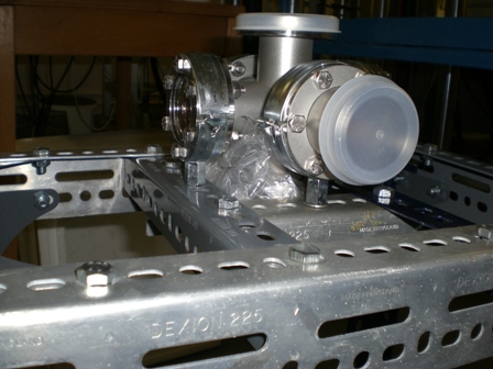
- Vacuum vessel attached to support structure:

- Close up view of how vacuum vessel is attached.:
- Viewports:

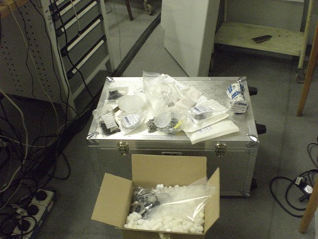
- Crate containing manipulator, other equipment that might be needed is placed on top:
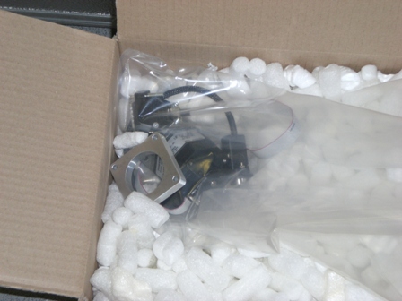
- Motors in box. The aluminium spacer plate is for the motor that controls the rotation. This might be slightly under thickness, if that is the case use washers to pack it out to the correct thickness.:
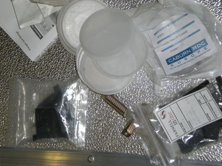
- Gaskets, connectors etc. Shown on top of crate.:


| I | Attachment | History | Action | Size | Date | Who | Comment |
|---|---|---|---|---|---|---|---|
| |
CIMG0994.JPG | r1 | manage | 95.0 K | 2008-01-25 - 20:52 | GeorgeEllwood | Vacuum vessel attached to support structure |
| |
CIMG0996.JPG | r1 | manage | 101.3 K | 2008-01-25 - 20:53 | GeorgeEllwood | Close up view of how vacuum vessel is attached. |
| |
CIMG0999.JPG | r1 | manage | 84.2 K | 2008-01-25 - 20:54 | GeorgeEllwood | Viewports |
| |
CIMG1000.JPG | r1 | manage | 78.4 K | 2008-01-25 - 20:56 | GeorgeEllwood | Crate containing manipulator, other equipment that might be needed is placed on top |
| |
CIMG1002.JPG | r1 | manage | 84.9 K | 2008-01-25 - 20:58 | GeorgeEllwood | Motors in box. The aluminium spacer plate is for the motor that controls the rotation. This might be slightly under thickness, if that is the case use washers to pack it out to the correct thickness. |
| |
CIMG1003.JPG | r1 | manage | 110.1 K | 2008-01-25 - 20:59 | GeorgeEllwood | Gaskets, connectors etc. Shown on top of crate. |
Topic revision: r3 - 2008-01-25 - GeorgeEllwood
- ABATBEA
- ACPP
- ADCgroup
- AEGIS
- AfricaMap
- AgileInfrastructure
- ALICE
- AliceEbyE
- AliceSPD
- AliceSSD
- AliceTOF
- AliFemto
- ALPHA
- Altair
- ArdaGrid
- ASACUSA
- AthenaFCalTBAna
- Atlas
- AtlasLBNL
- AXIALPET
- CAE
- CALICE
- CDS
- CENF
- CERNSearch
- CLIC
- Cloud
- CloudServices
- CMS
- Controls
- CTA
- CvmFS
- DB
- DefaultWeb
- DESgroup
- DPHEP
- DM-LHC
- DSSGroup
- EGEE
- EgeePtf
- ELFms
- EMI
- ETICS
- FIOgroup
- FlukaTeam
- Frontier
- Gaudi
- GeneratorServices
- GuidesInfo
- HardwareLabs
- HCC
- HEPIX
- ILCBDSColl
- ILCTPC
- IMWG
- Inspire
- IPv6
- IT
- ItCommTeam
- ITCoord
- ITdeptTechForum
- ITDRP
- ITGT
- ITSDC
- LAr
- LCG
- LCGAAWorkbook
- Leade
- LHCAccess
- LHCAtHome
- LHCb
- LHCgas
- LHCONE
- LHCOPN
- LinuxSupport
- Main
- Medipix
- Messaging
- MPGD
- NA49
- NA61
- NA62
- NTOF
- Openlab
- PDBService
- Persistency
- PESgroup
- Plugins
- PSAccess
- PSBUpgrade
- R2Eproject
- RCTF
- RD42
- RFCond12
- RFLowLevel
- ROXIE
- Sandbox
- SocialActivities
- SPI
- SRMDev
- SSM
- Student
- SuperComputing
- Support
- SwfCatalogue
- TMVA
- TOTEM
- TWiki
- UNOSAT
- Virtualization
- VOBox
- WITCH
- XTCA
 |
|
or Ideas, requests, problems regarding TWiki? use Discourse or Send feedback