Creating an Assembly of Volumes
G4AssemblyVolume is a helper class which allows several logical
volumes to be combined together in an arbitrary way in 3D space. The
result is a placement of a normal logical volume, but where final
physical volumes are many.
However, an assembly volume does not act as a real mother volume, being an envelope for its daughter volumes. Its role is over at the time the placement of the logical assembly volume is done. The physical volume objects become independent copies of each of the assembled logical volumes.
This class is particularly useful when there is a need to create a
regular pattern in space of a complex component which consists of
different shapes and can’t be obtained by using replicated volumes or
parametrised volumes (see also Fig. 9.
Careful usage of G4AssemblyVolume must be considered though, in order
to avoid cases of “proliferation” of physical volumes all placed in the
same mother.
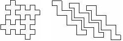
Fig. 9 Examples of assembly of volumes.
Filling an assembly volume with its “daughters”
Participating logical volumes are represented as a triplet of <logical
volume, translation, rotation> (G4AssemblyTriplet class).
The adopted approach is to place each participating logical volume with respect to the assembly’s coordinate system, according to the specified translation and rotation.
Assembly volume placement
An assembly volume object is composed of a set of logical volumes; imprints of it can be made inside a mother logical volume.
Since the assembly volume class generates physical volumes during each
imprint, the user has no way to specify identifiers for these. An
internal counting mechanism is used to compose uniquely the names of the
physical volumes created by the invoked MakeImprint(...) method(s).
The name for each of the physical volume is generated with the following format:
av_WWW_impr_XXX_YYY_ZZZ
where:
WWW - assembly volume instance number
XXX - assembly volume imprint number
YYY - the name of the placed logical volume
ZZZ - the logical volume index inside the assembly volume
It is however possible to access the constituent physical volumes of an assembly and eventually customise ID and copy-number.
The setting of the copy-numbers can be complex, depending on how
complex is the structure being built. Each assembly (G4AssemblyVolume)
instance gets automatically assigned a number, assemblyID, which
starts from zero and gets incremented based on the number of imprints
being made. Each assembly is being stored in a G4AssemblyStore and
can always been retrieved at any time.
G4AssemblyVolume allows to define a base copy-number for each
imprint (call to MakeImprint()), by specifying it as a parameter,
copyNumBase, which is set to zero by default.
The computation of the effective copy-number of each volume in the
assembly is done using such parameter, i.e. based on the number of
triplets (number of volumes added in the assembly), each volume
copy number is assigned as:
numberOfDaughters + i
where i goes from zero to the number of volumes in the assembly;
numberOfDaughters is either set to the number of daughter volumes
in the mother where the assembly must be placed (if copyNumBase is
zero, i.e. not being specified at the time the imprint is made), or
the specified copyNumBase.
In case the assembly includes another assembly inside, the call
to makeImprint() is made recursively, and the base copy-number
in this case is being set to:
i*100+copyNumBase
so, shifted by 100 times the index of the triplet in the original assembly.
Destruction of an assembly volume
At destruction all the generated physical volumes and associated
rotation matrices of the imprints will be destroyed. A list of physical
volumes created by MakeImprint() method is kept, in order to be able
to cleanup the objects when not needed anymore. This requires the user
to keep the assembly objects in memory during the whole job or during
the life-time of the G4Navigator, logical volume store and physical
volume store may keep pointers to physical volumes generated by the
assembly volume.
The MakeImprint() method will operate correctly also on
transformations including reflections and can be applied also to
recursive assemblies (i.e., it is possible to generate imprints of
assemblies including other assemblies). Giving true as the last
argument of the MakeImprint() method, it is possible to activate the
volumes overlap check for the assembly’s constituents (the default is
false).
Each assembly structure is registered at construction in a specialised
store, G4AssemblyStore, which can then be used to identify all
structures defined in a geometry setup, as well as the volumes belonging
to each imprint.
At destruction of a G4AssemblyVolume, all its generated physical
volumes and rotation matrices will be automatically freed.
Example
This example shows how to use the G4AssemblyVolume class. It
implements a layered detector where each layer consists of 4 plates.
In the code below, at first the world volume is defined, then solid and logical volume for the plate are created, followed by the definition of the assembly volume for the layer.
The assembly volume for the layer is then filled by the plates in the same way as normal physical volumes are placed inside a mother volume.
Finally the layers are placed inside the world volume as the imprints of the assembly volume (see Listing 41).
static unsigned int layers = 5;

void TstVADetectorConstruction::ConstructAssembly()
{
  // Define world volume
  G4Box* WorldBox = new G4Box( "WBox", worldX/2., worldY/2., worldZ/2. );
  G4LogicalVolume*   worldLV  = new G4LogicalVolume( WorldBox, selectedMaterial,
                                                    "WLog", 0, 0, 0 );
  G4VPhysicalVolume* worldVol = new G4PVPlacement( 0, G4ThreeVector(), "WPhys",worldLV,
                                                  0, false, 0 );

  // Define a plate
  G4Box* PlateBox = new G4Box( "PlateBox", plateX/2., plateY/2., plateZ/2. );
  G4LogicalVolume* plateLV = new G4LogicalVolume( PlateBox, Pb, "PlateLV", 0, 0, 0 );

  // Define one layer as one assembly volume
  G4AssemblyVolume* assemblyDetector = new G4AssemblyVolume();

  // Rotation and translation of a plate inside the assembly
  G4RotationMatrix Ra;
  G4ThreeVector Ta;
  G4Transform3D Tr;

  // Rotation of the assembly inside the world
  G4RotationMatrix Rm;

  // Fill the assembly by the plates
  Ta.setX( caloX/4. ); Ta.setY( caloY/4. ); Ta.setZ( 0. );
  Tr = G4Transform3D(Ra,Ta);
  assemblyDetector->AddPlacedVolume( plateLV, Tr );

  Ta.setX( -1*caloX/4. ); Ta.setY( caloY/4. ); Ta.setZ( 0. );
  Tr = G4Transform3D(Ra,Ta);
  assemblyDetector->AddPlacedVolume( plateLV, Tr );

  Ta.setX( -1*caloX/4. ); Ta.setY( -1*caloY/4. ); Ta.setZ( 0. );
  Tr = G4Transform3D(Ra,Ta);
  assemblyDetector->AddPlacedVolume( plateLV, Tr );

  Ta.setX( caloX/4. ); Ta.setY( -1*caloY/4. ); Ta.setZ( 0. );
  Tr = G4Transform3D(Ra,Ta);
  assemblyDetector->AddPlacedVolume( plateLV, Tr );

  // Now instantiate the layers
  for( unsigned int i = 0; i < layers; i++ )
  {
    // Translation of the assembly inside the world
    G4ThreeVector Tm( 0,0,i*(caloZ + caloCaloOffset) - firstCaloPos );
    Tr = G4Transform3D(Rm,Tm);
    assemblyDetector->MakeImprint( worldLV, Tr );
  }
}
The resulting detector will look as in Fig. 10.
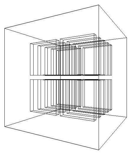
Fig. 10 The geometry corresponding to the Listing 41.