Instructions for ALICE TOF shifters
- ACR telephone 76753
- Andrea's mobile 165850
- Gilda's mobile 162836
Shifter tasks
The shifter should check regularly various hardware parameters status : HV , LV , gas, cooling, temperatures. Compare them with reference values as reported below. PLEASE DO NOT TRY TO MODIFY ANYTHING UNLESS YOU ARE VERY SURE OF WHAT YOU ARE DOING. The shifter should know what is happening in ALICE. Refer to the ALICE elog (https://alice-logbook.cern.ch- runs: specify start/end time, trigger, readout components, magnetic field
- errors/problems with as many details ( also screen dumps).
- ----> at the end of the shift write a mini summary of what happened (also in ALICE) during the shift. <---- THIS IS VERY VERY IMPORTANT !!!!!
Preliminary Instructions
The machine devoted to monitoring and shifters general operations is ALITOFON001. The machine is reachable via remote desktop from the DAQ Linux machine located in the ACR. All of you should have an active account on this machine, otherwise if you accidentally close the windows you have to call the on-call expert (not advisable especially during the night...). On the DAQ Linux machine the TOF account is: username: tofpassword: XXXXXXX The command for remote desktop could be for example (for a two-screen wide panel): rdesktop -a16 -g2580x980 alitofon001 On this machine there are the following useful panels that could be opened (some of them HAVE TO BE OPENED):
- the TOF DCS_UI is the mirror of the main TOF DCS projects. If you are not granted to log into this panel please call me (Andrea). Different users may have different privileges, so each shifter must logout from this panel at the end of his shift. You should use this panel to monitor the state of the TOF FSM and to turn OFF/ON part of the detector, i.e. LV, FEE, HV... I advise you to send commands using the FSM Controls and always from the TOP NODE. To enable the FSM Controls click with the mouse right button on the item in the tree and select "view panel". If you right-click a second time, you can select the "open fsm control" too.
- the TOF BasePanel (you can launch it from the START Menu) is the main panel for monitoring the "hardware" status of TOF. From here, you can monitor the status of the LV, HV, gas systems..., the temperatures of the FE and RO electronics, look at the status of the cooling plant and so on.
- the tofAlarms panel is a very important one. This panel is (at the moment) the only way to handle all the TOF alarms and to trigger automatic procedures to avoid big hardware damages. As an example, the automatic procedures to turn off crates when their temperatures become too high run inside this panel. VERY IMPORTANT: THIS PANEL MUST BE ALWAYS RUNNING, BUT ONLY FROM THE MACHINE IN THE ACR. DO NOT RUN THIS PANEL FROM A DIFFERENT PC IN OUR OFFICE, OR YOU CAN GENERATE UNDESIRABLE SITUATIONS. The panel is reachable from the path D:\utils\tofAlarms.bat
- From D:\utils\alarmScreen.bat you can run the panel which display in real-time all the active TOF alarms.
Reference Hardware Parameters
Clicking on the link above you will find useful reference panels to compare with the ones available during your shift. These plots are updated by the experts whenever the various parameters are changed.General Overview
The core of the DCS is based on Finite State Machine (FSM). A FSM is an intuitive, generic mechanism to model the functionality of a piece of equipment or a sub-system. The entity to be modelled is thought of as having a set of stable ‘states’. It can move between these states by executing ‘actions’ that are triggered either by commands from an operator or another component or by other events such as state changes of other components. The control system is build as a tree-like structure. Communication between the different nodes in the tree (the control and device units) is performed via a well defined, so called, state/command interface. Commands will propagate from the highest levels through the control units to end in the device units where action on the real hardware is performed. In each control unit appropriate behaviour can be programmed with the FSM upon the reception of a command. This allows the use of ‘generic’ commands (commands that are independent of the actual sub-detector or sub-system such as ‘prepare for physics’) on the higher levels of the control hierarchy. The control unit will then send the appropriate commands to its children. States will propagate from the lower levels to the higher levels. Upon receiving or reading a change in one or more parameters of a device, the device unit can change its state to reflect this. The parent control unit can react on this state change and, depending on the behaviour programmed in the control unit with the FSM, change its state to propagate the information. In parallel the control unit can also act on this and/or other children. This mechanism allows the propagation of state changes up to the highest level, while at each level states can be correlated with the states of other sub-trees. The set of all disposable states for TOF DCS is (and the shifters and anyone else MUST STRICLY follow the exact sequence powering ON and OFF the detector) is: OFF --> STANDBY --> STBY_CONFIGURED --> BEAM_TUNING (optional) --> READY OFF means that the whole detector is switched OFF. In the STANDBY state all the LV channels and the VME slots are powered ON. In the STBY_CONFIGURED important checks and configurations on all the VME boards are performed. BEAM_TUNING means essentially electronics ready but HV OFF (safe condition for beam injection). In the READY state the detector is finally ready for taking data. During beam periods this state is associated with a SAFE state for TOF, i.e. with HV < 1000 V. Full HV will be applied manually when appropriate. A set of command is defined as well: GO_OFF, GO_STANDBY, GO_STBY_CONF, GO_BEAM_TUNING and GO_READY. During a state transition the will assume one of the following transient state: MOVING_OFF, MOVING_STANDBY, MOVING_STBY_CONF, MOVING_BEAM_TUNING, MOVING_READY For remote control and monitoring of all equipments a set of operator interface panels have been created. The panels that have to be always opened and running are: the DCS UI panel, the BasePanel and the TofAlarms (they are launchable from the Windows Start Menù).General Operations
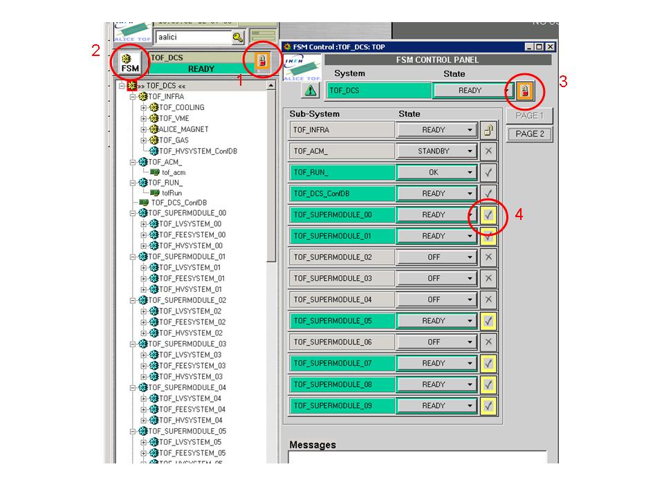
Let us suppose that such is the case: the TOF is in OFF state and you are asked to set it to READY. The panel you need to send the correct commands is (I repeat it over and over again) the DCS UI panel. Well, this is what you will be asked to do:- (1) open the TOP NODE panel in the DCS UI from the FSM Hierarchy Tree Browser then open the FSM control panel ( right button on >> TOF DCS << then OPEN FSM CONTROL)
- (2) be sure to have the control of the TOF DCS. If the general lock is red painted, it means that the TOF is owned by someone else (DCS, ECS or DAQ). Ask them to release the control and take it!
- (3) send the command GO_STANDBY from the TOP NODE. The LV channels and in succession the VME slots are switched ON. You can use the TOF BasePanel to monitor the execution of the command. For example, looking at the LV you can see all the selected LV channels switching ON. In the same way from the FEE panel you can check if all the VME slots are turned ON correctly.
- (4) if all it's ok, the status TOF DCS will become STANDBY, otherwise it will be different (tipically MIXED). Use the BasePanel to find what's wrong.
- (5) now, in the same way as before you can apply a GO_STBY_CONF and a GO_READY commands.
More details on Panels
DSC UI
DCS UI documentation (ver. 3.0.2): This panel allows to monitor the state of the TOF FSM and to send commands from the highest level of the hierarchy (TOP NODE) to all sub-nodes and devices. On the top left part the actual status is displayed, as well as if the panel is locked (red) or not by the central DCS: this is the status that allows ALICE to use TOF in the runs. If unlocked then the TOF DCS is under our control.
- User Login
- FSM node control
- FSM Hierarchy Tree Browser
If commands have to be issued push the FSM Node Control button.
- Alarm Panel
- InfoBrowser

- FSM Expert Controls

TofAlarms Panel
To get this panel go on the Windows START and look for the tofAlarms.bat process.
Standard Alarm Panel
You can run this panel from the specific button in the DCS UI panel.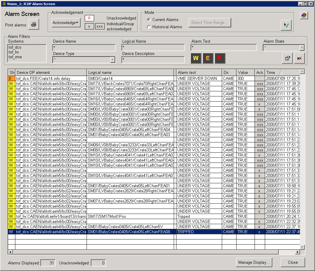 In this panel you can find informations that could help you in fixing the problems. More in details:
- The 3th column display the logical name of the object falled in an error state;
- The 4th column display a short description of what kind of error is (connection, temperature, LV...)
To display only the TOF alarms one have to use the appropriate filter.

- Click on the
Modify Filterbutton (1); - Click on the
Open folderbutton (2); - Select the
toffilter andloadit (3); - Apply the filter (4).
PVSS Alarm Panel
You can run this panel from D:\utils\alarmScreen.bat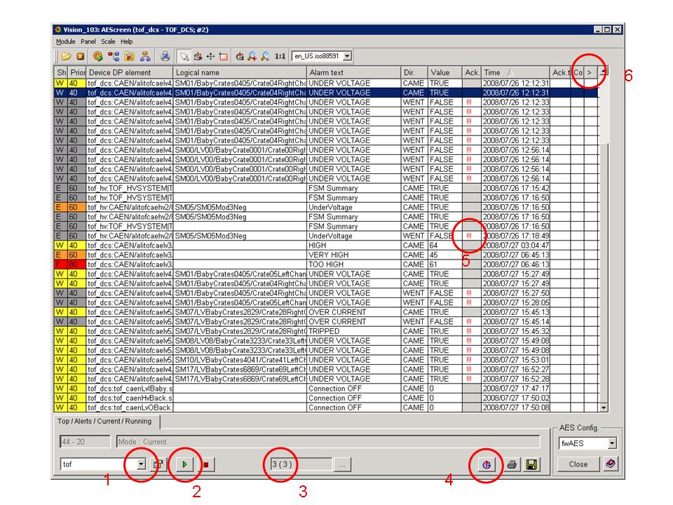
- (1) select the filter called
tof; - (2) run the panel;
- (3) here you can check if all the three TOF system (DCS, HV and VME) are running;
- (4) from here you can acknowledge all the visible alarms, or
- (5) click with the mouse right button here you can acknowledge just one particular alarm;
- (6) if you click on this column a panel with explanation on this particular alarm opens, as for example
 Here you can find a list of alarm and some istruction to how to fix it!
Alarm List
- Connections
- DIM server crate#
- VME server crate #
- Status RDB Manager (Oracle DB)
- Status Distribution Managers
- Status Linux PCs
- Status PVSS DIM Managers
- HV System
- Alarm on current values
- Over Current
- Trip
- Under Voltage
- LV System
- Over Current
- Trip
- Under Voltage
- A1396 Temperature (with action on LV channel)
- DRM, LTM and TRM Temperature (No Standard Alarm but action on VME boards)
- Cooling System
- Cooling Water Temperature
- Loops Status (with action on CANE Power Supplies)
- Gas System
Alarm Description
- Under Voltage
How to fix it: find which channel is in error reading the logical name of the object. Using the FSM Hierarchy Tree Browser find the relevant node and open the operational panel. Try to switch OFF and ON again tha channel, or get a Clear Alarm. If the error persit, you have to exclude the object from the TOF DCS Project.
- Over Curent
How to fix it: find which channel is in error reading the logical name of the object. Using the FSM Hierarchy Tree Browser find the relevant node and open the operational panel. Try to switch OFF and ON again tha channel, or get a Clear Alarm. If the error persit, you have to exclude the object from the TOF DCS Project.
- TRIPPED
How to fix it: find which channel is in error reading the logical name of the object. Using the FSM Hierarchy Tree Browser find the relevant node and open the operational panel. Try to switch OFF and ON again tha channel, or get a Clear Alarm. If the error persit, you have to exclude the object from the TOF DCS Project.
- VME Server Down
How to fix it: find to which crate the ddl belong and open the corresponding operational panel (there is also a link from the tofAlarms panel, see picture below). Click on the
VME server restart. If the problem persist you have to switch OFF the whole crate because the board temperature are not monitored so far!
- DIM Server Down
How to fix it: find to which crate the ddl belong and open the corresponding operational panel (there is also a link from the tofAlarms panel, see picture below). Click on the
DIM restart. If the problem persist you have to switch OFF the whole crate because the board temperature are not monitored so far!
- ACM Server Down
How to fix it: open the ACM operational panel (there is also a link from the tofAlarms panel, see picture below) and click on the
ACM restart.
- INTERCOM Server Down
How to fix it: open one of the crate operational panel no matter which (there is also a link from the Base Panel panel in the CONNECTION section , see picture below) and click on the
INTERCOM restart.

Base Panel
Knowing the TOF hardware construction, most of the panels are selfexplaining. Please note that for LV and HV clicking on a channel the history will be available ( if the option "OPEN panel" on the right is selected).Miscellaneous
Get an error starting a panel
Sometimes an error occurs trying to open a panel and the following message appears:
 I don't know why it happens, but it's just a temporary problem. Usually trying several times or after few minutes it desappears...
How to exclude some objects
If the TOF DCS fall in an error state you may be forced to exclude part of the project. In order to do that you have to:- ask the DCS, DAQ or ECS people to release the control of the detector to you;
- go on the TOP NODE of the DCS UI and open the FSM controls;
- take the control of the FSM by clicking on the lock icon (look at (3) in the picture below);
- exclude the node by clicking on the corresponding icon (look at (4) in the picture below);
How to exclude HV channels from the FSM
Since the HV system FSM elements are imported from a different project it is not possible to incude/exclude HV channel from the FSM in the usual way. Instead of the FSM control we have to use the operational panel and the button enable/disable show in the picture below.
How to restart the FSM
If the TOF DCS become DEAD you have to restart the FSM. Click on the button "FSM expert controls" in the DCS UI panel and select "Start/Restart All".The process could take times; be patient.
How to apply a recipe
In the TOF DCS there are 2 Configurator: the INFRA/TOF_HVSYSTEM_ConfDB for the HV system and the TOF_DCS_ConfDB for the LV system. The standard recipe for LV setup is applied automatically before to switch ON the crates. For the HV setup you can do it manually from the FSM control; give the command LOAD and select the recipe you want to apply. The DB panel (see below) may help you; selecting the name of the recipe, a small description is given in theRecipe description field. Just type the name of the recipe in the popup window and go.

How to monitor PVSS managers
If you would like to monitor or manage the status of the PVSS managers or to restart the whole project, you can connect directly to the PMON using a web browser and select the address:- http://alitofwn001.cern.ch:4999
 for TOF_DCS
- http://alitofwn002.cern.ch:4999 for TOF_HV
- http://alitofwn003.cern.ch:4999 for TOF_VME
How to extract errors from the DAQ_SITE infoBrowser
It is likely in your shift report you want to report error messages from the infoBrowser (both the ALICE DAQ or the TOF one). To select a portion of messages and save it in a file follow this procedure:- decide which messages you want to extract

- deselect the online bottom
- typically use the following keys to get only the messages you want: min Time, Level, Facility, then push Query

- once you have the entries you want to save, push "export" and save them in a file. The file with the error is pure text and it can be usefully sent as an attach in log entry.


| I | Attachment | History | Action | Size | Date | Who | Comment |
|---|---|---|---|---|---|---|---|
| |
AlarmScreenFilter.jpg | r1 | manage | 101.2 K | 2008-07-12 - 12:24 | AndreaAlici | |
| |
DB.PNG | r1 | manage | 24.1 K | 2008-07-22 - 14:52 | AndreaAlici | |
| |
DCS_UI.jpg | r1 | manage | 91.8 K | 2008-07-12 - 10:15 | AndreaAlici | |
| |
aes.jpg | r1 | manage | 185.3 K | 2008-07-27 - 21:54 | AndreaAlici | |
| |
alarm1.PNG | r1 | manage | 96.0 K | 2008-07-12 - 12:24 | AndreaAlici | |
| |
alertMsg.PNG | r1 | manage | 21.5 K | 2008-07-27 - 21:54 | AndreaAlici | |
| |
checkConn.PNG | r1 | manage | 34.6 K | 2008-07-12 - 13:21 | AndreaAlici | |
| |
control.PNG | r2 r1 | manage | 56.9 K | 2008-09-09 - 18:55 | AndreaAlici | |
| |
dcsUi.PNG | r1 | manage | 262.4 K | 2008-09-09 - 18:57 | AndreaAlici | |
| |
exclude.jpg | r2 r1 | manage | 100.8 K | 2008-07-22 - 15:15 | AndreaAlici | |
| |
exclude.png | r1 | manage | 184.3 K | 2008-07-12 - 15:51 | AndreaAlici | |
| |
exclude2.PNG | r1 | manage | 26.1 K | 2008-07-12 - 15:52 | AndreaAlici | |
| |
hv_exclude.jpg | r1 | manage | 71.6 K | 2008-08-06 - 02:10 | AndreaAlici | |
| |
infoBrowser.PNG | r1 | manage | 67.7 K | 2008-09-09 - 18:57 | AndreaAlici | |
| |
infoBrowser1.jpg | r1 | manage | 203.5 K | 2008-08-21 - 19:41 | PietroAntonioli | |
| |
infoBrowser2.jpg | r1 | manage | 95.8 K | 2008-08-21 - 19:42 | PietroAntonioli | |
| |
lengths-sm18bis.pdf | r1 | manage | 26.0 K | 2008-07-29 - 09:02 | AndreaAlici | |
| |
tofAlarms.PNG | r1 | manage | 40.7 K | 2008-07-12 - 13:22 | AndreaAlici | |
| |
unexpected.PNG | r1 | manage | 105.1 K | 2008-07-12 - 13:22 | AndreaAlici |
Topic revision: r29 - 2009-07-05 - OmbrettaPinazza
-
 AliceTOF Web
 - AliceTOFDCS
- Other topics
-
 Create New Topic
-
 Index
Index
-
 Search
-
 Changes
-
 Notifications
-
 Statistics
-
 Preferences
- ABATBEA
- ACPP
- ADCgroup
- AEGIS
- AfricaMap
- AgileInfrastructure
- ALICE
- AliceEbyE
- AliceSPD
- AliceSSD
- AliceTOF
- AliFemto
- ALPHA
- Altair
- ArdaGrid
- ASACUSA
- AthenaFCalTBAna
- Atlas
- AtlasLBNL
- AXIALPET
- CAE
- CALICE
- CDS
- CENF
- CERNSearch
- CLIC
- Cloud
- CloudServices
- CMS
- Controls
- CTA
- CvmFS
- DB
- DefaultWeb
- DESgroup
- DPHEP
- DM-LHC
- DSSGroup
- EGEE
- EgeePtf
- ELFms
- EMI
- ETICS
- FIOgroup
- FlukaTeam
- Frontier
- Gaudi
- GeneratorServices
- GuidesInfo
- HardwareLabs
- HCC
- HEPIX
- ILCBDSColl
- ILCTPC
- IMWG
- Inspire
- IPv6
- IT
- ItCommTeam
- ITCoord
- ITdeptTechForum
- ITDRP
- ITGT
- ITSDC
- LAr
- LCG
- LCGAAWorkbook
- Leade
- LHCAccess
- LHCAtHome
- LHCb
- LHCgas
- LHCONE
- LHCOPN
- LinuxSupport
- Main
- Medipix
- Messaging
- MPGD
- NA49
- NA61
- NA62
- NTOF
- Openlab
- PDBService
- Persistency
- PESgroup
- Plugins
- PSAccess
- PSBUpgrade
- R2Eproject
- RCTF
- RD42
- RFCond12
- RFLowLevel
- ROXIE
- Sandbox
- SocialActivities
- SPI
- SRMDev
- SSM
- Student
- SuperComputing
- Support
- SwfCatalogue
- TMVA
- TOTEM
- TWiki
- UNOSAT
- Virtualization
- VOBox
- WITCH
- XTCA
 |
|
or Ideas, requests, problems regarding TWiki? use Discourse or Send feedback