Architecture of the LHCb Upgrade trigger
The LHCb upgrade trigger uses a two-stage architecture illustrated in the following figure
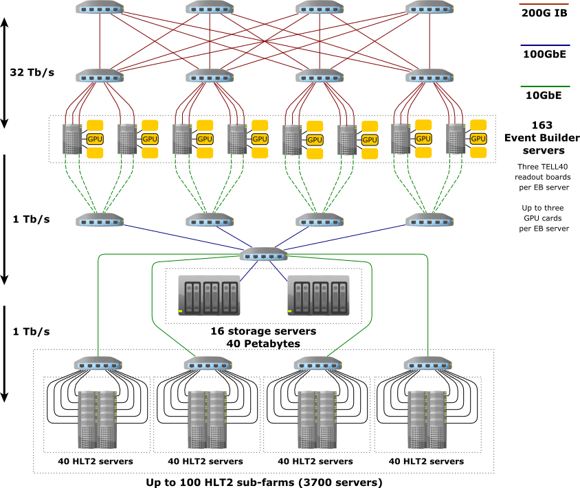
The detector data is received by 163 “event building” (EB) servers, each of which hosts up to three custom TELL40 readout boards. Each board receives data from one part of the detector. The EB servers are connected by a dedicated network which allows these event data fragments to be built into full LHCb events. This aggregation occurs inside the EB server memory, and both the amount of memory and the memory bandwidth must be sufficient to handle peak data rates. For this reason EB servers are equipped with 512 Gigabytes of RAM each. These events are then aggregated into “multi-event packets” (MEPs) before being passed on for further processing. The number of events or bunch crossings in a MEP is a tunable parameter of the system but is typically around 1000 events each. Passing MEPs instead of individual events minimizes I/O overheads in the system.
The first trigger stage (HLT1) is implemented in GPUs, which are hosted in the same EB nodes as the readout boards. For 2022 datataking the system consists of one GPU card per EB node, while up to three can be physically hosted. More information about this processing stage can be found in the Allen documentation. This stage reduces the overall data rate by a factor 15-30. It selects full LHCb Upgrade events which are then buffered to a disk buffer with 45.7 Petabyte raw capacity while the detector alignment and calibration are performed. The disk buffer is hosted in a set of dedicated disk servers which are not used for processing.
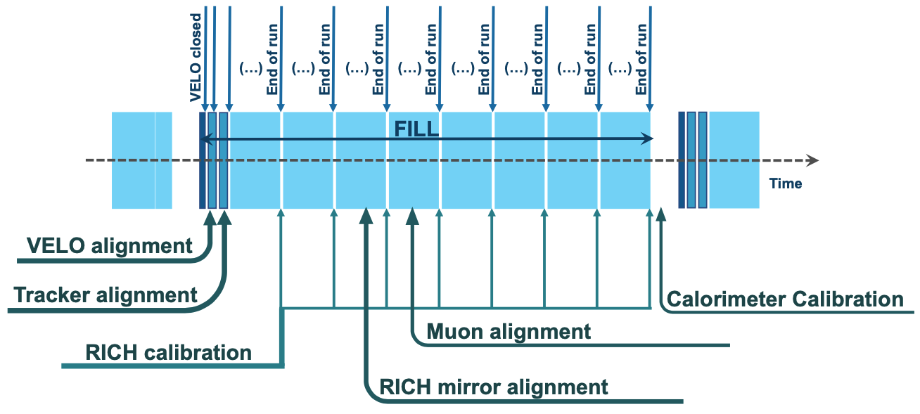
A subset of the events selected by HLT1 are themselves used as inputs to the alignment and calibration algorithms. To give just a few examples: a sample of unbiased collision events with hits in the VELO are used to align the VELO; events enriched in Cabibbo-favoured charm decays and \(J/\psi \to \mu^{+}\mu^{-}\) decays are used to align the tracking system; a subset of events whose tracks are equally distributed across the RICH acceptance are used to align the RICH mirrors. The picture below shows a rough timeline of when each step of the alignment and calibration is executed relative to one LHC fill.
Once the detector alignment and calibration are available for a given run, the events selected by HLT1 are made available to the second trigger stage (HLT2) which is implemented on a farm of around 3700 CPU servers. At the same time these latest alignment and calibration constants are given to HLT1 and a new run is started. The disk buffer allows HLT2 processing to occur independently of whether the LHC is colliding or not, increasing the effective processing power of these servers. HLT2 outputs around 10 Gigabytes of data per second for offline processing. More details about the LHCb Upgrade dataflow can be found in the Starterkit documentation.
Scalability of the LHCb Upgrade trigger
The LHCb trigger architecture has been designed to be scalable and upgradable. Here we will describe the boundary conditions present in the different parts of the system.
Scalability of HLT1 processing power
There are three ways to add processing power to HLT1: replace the existing GPU cards with more powerful versions, add GPU cards, and add EB servers which can host GPU cards. The fundamental rule which has to be respected is that each EB server must have approximately the same network I/O rate of events, so in practice each must host the same mixture of GPU cards. Up to three GPU cards can be hosted in each EB server. Beyond the 163 EB servers used to host FPGA cards which read out the detector, additional servers can be added which host only GPU cards. The total EB network is limited to around 200 servers, and around 10 servers are required to be on standby as “hot swaps” in case a server with one of the readout cards fails. This means that 27 additional servers hosting only GPU cards, or around 15% of the system capacity, can be deployed taking the total system size to 190 EB nodes.
Scalability of the HLT1 output rate
Each EB node has two 10 Gigabit links which can be used to send data to the disk buffer. In the baseline system one link is used to transfer HLT1 accepted events. We know from Run 1 and 2 that HLT1 selects slightly bigger events, so we assume 120 kilobytes as the size of an HLT1 accepted event. With the maximum of 190 EB nodes this gives a limit of around 1.9 Terabits per second or roughly 2 MHz of events which can be selected by HLT1. This limit could be increased by enabling part of the second link to be used for the data transfer.
A second limitation comes from the disk buffer read-write speeds, because the disk buffer has to handle burst data rates without dropping events. The 40 Petabyte buffer consists of around 3000 physical drives and can safely sustain write speeds of around 1 Terabit per second or around 1 MHz of events. This is the single most restrictive boundary condition in the LHCb Upgrade trigger architecture. Increasing the number of disk drives is both expensive (around 1 MCHF per 1 MHz of extra events) and requires freeing up some space in the data centre by removing some HLT2 processing nodes.
Scalability of HLT2 processing power
The baseline system fully fills the available space in the data centre with HLT2 servers, and so physically upgrading the system requires replacing old servers with newer ones. This imposes an effective “tax” on money which is spent to upgrade HLT2. A small amount of extra capacity could be deployed by reusing the old D1 underground server room, corresponding to around 20% of the overground data centre.
The main way to extend the processing power of HLT2 is to use the disk buffer, which at an HLT1 accept rate of 1 MHz can store around 90 hours of HLT1 accepted events. We can then simulate the LHC fill structure seen in Run 2 and calculate how much effective processing power this disk buffer adds by allowing HLT1 accepted events to be processed outside LHC collisions. The answer is roughly a factor two. At the time of writing the fastest HLT2 configuration could process around 300 Hz of HLT1 accepted events on a reference HLT2 server node, so taking this doubling into account roughly 2.5 MHz of HLT1 accepted events can be processed by the baseline HLT2 system.
Further reading
A Comparison of CPU and GPU implementations for the LHCb Experiment Run 3 Trigger