Format:
BOX  CENTRE cx cy cz ...
     HALF-LENGTHS lx ly lz ...
     [DIRECTION dx dy dz] ...
     [VOLTAGE v] ...
     [FLOATING-CONDUCTOR] ...
     [CHARGE q] ...
     [EPSILON eps] ...
     [material] ...
     [LABEL label]
     [FRONT-DISCRETISATION discretisation] ...
     [BACK-DISCRETISATION discretisation] ...
     [RIGHT-DISCRETISATION discretisation] ...
     [LEFT-DISCRETISATION discretisation] ...
     [TOP-DISCRETISATION discretisation] ...
     [BOTTOM-DISCRETISATION discretisation]
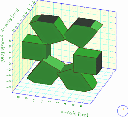
Illustration:
A set of boxes that are intersecting each other. Shown using the default colour density table, with outlining.
Additional information on:
For many purposes, cylinders and wires are equivalent, but the differences are important when using neBEM to compute the field:
Mandatory parameters are the location of the centre, the radius and the length. The direction defaults to the z-axis.
Format:
CYLINDER  CENTRE cx cy cz ...
          RADIUS radius ... ...
          [OUTER-RADIUS | MEAN-RADIUS]
          HALF-LENGTH lz ...
          [DIRECTION dx dy dz] ...
          [VOLTAGE v] ...
          [FLOATING-CONDUCTOR] ...
          [CHARGE q] ...
          [EPSILON eps] ...
          [material] ...
          [LABEL label] ...
          [ROTATE angle] ...
          [N n] ...
          [TOP-LID-DISCRETISATION discretisation] ...
          [BODY-DISCRETISATION discretisation] ...
          [BOTTOM-LID-DISCRETISATION discretisation] ...
          [TOP-LID | NOTOP-LID] ...
          [BOTTOM-LID | NOBOTTOM-LID] ...
          [LIDS | NOLIDS]
Illustration:
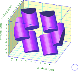
A set of cylinders, partially hiding each other. Each cylinder is drawn with 50 panels, and 20 colour shades are used.
Additional information on:
Mandatory parameters are the extrusion profile and the half-length. The direction defaults to the z-axis and the central position to (0,0,0).
Format:
EXTRUSION  CENTRE cx cy cz ...
           HALF-LENGTH lz ...
           PROFILE x1 y1  x2 y2  x3 y3 ... xn yn ...
           [DIRECTION dx dy dz] ...
           [VOLTAGE v] ...
           [FLOATING-CONDUCTOR] ...
           [CHARGE q] ...
           [EPSILON eps] ...
           [material] ...
           [LABEL label] ...
           [TOP-LID-DISCRETISATION discretisation] ...
           [BODY-DISCRETISATION discretisation] ...
           [BOTTOM-LID-DISCRETISATION discretisation] ...
           [TOP-LID | NOTOP-LID] ...
           [BOTTOM-LID | NOBOTTOM-LID] ...
           [LIDS | NOLIDS]
Illustration:
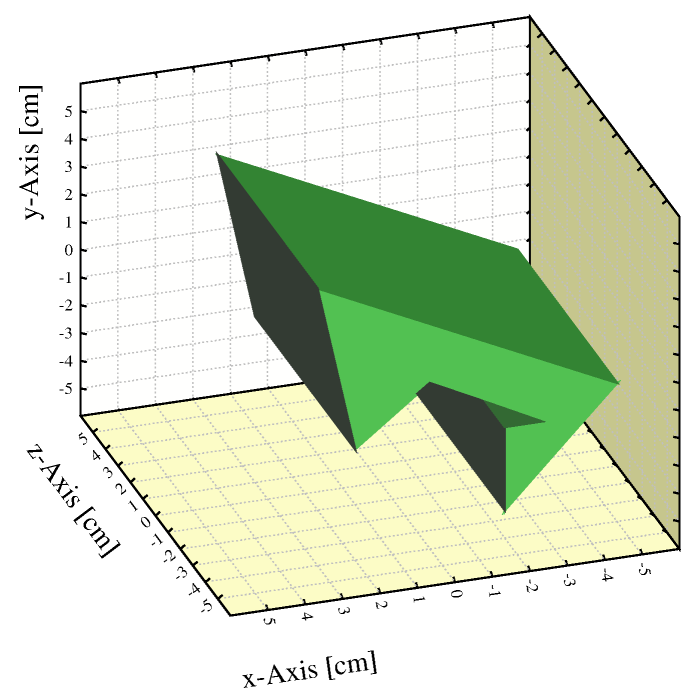
An extrusion
&CELL
nebem target-element-size 1
solids
box centre        0   0  10 ...
    half-lengths 10  10   0 ...
    volt          0
box centre        0   0 -10 ...
    half-lengths 10  10   0 ...
    volt          0
extrusion centre  0  0  0 ...
    half-length   4 ...
    profile       -5 -1   -2 -5   -2 -2  -3 -2   0 0    2 -2    3 4 ...
    voltage       1

opt cell-print
&FIELD
area -6 -6 -6 6 6 6 view x+2*y-3*z=0 nebem
Call plot_field_area
Call plot_end
Additional information on:
Format:
HOLE  CENTRE cx cy cz ...
      RADIUS radius | UPPER-RADIUS r_up LOWER-RADIUS r_low ...
      [OUTER-RADII | MEAN-RADII]
      HALF-LENGTHS lx ly lz ...
      [DIRECTION dx dy dz] ...
      [VOLTAGE v] ...
      [FLOATING-CONDUCTOR] ...
      [CHARGE q] ...
      [EPSILON eps] ...
      [material] ...
      [LABEL label] ...
      [N n]
      [FRONT-DISCRETISATION discretisation] ...
      [BACK-DISCRETISATION discretisation] ...
      [RIGHT-DISCRETISATION discretisation] ...
      [LEFT-DISCRETISATION discretisation] ...
      [TOP-DISCRETISATION discretisation] ...
      [BOTTOM-DISCRETISATION discretisation] ...
      [CYLINDER-DISCRETISATION discretisation]
Illustration:
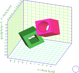
Two holes, on the left with N=2, on the right with N=20. Both are drawn with outlining.
Additional information on:
The ridge proper is by default aligned with the y-axis, the (x,y) plane is taken to the floor of the construction.
Format:
RIDGE  CENTRE cx cy cz ...
       HALF-LENGTHS lx ly ...
       NOTCH rx rz ...
       [DIRECTION dx dy dz] ...
       [VOLTAGE v] ...
       [FLOATING-CONDUCTOR] ...
       [CHARGE q] ...
       [EPSILON eps] ...
       [material] ...
       [LABEL label]
       [FRONT-DISCRETISATION discretisation] ...
       [BACK-DISCRETISATION discretisation] ...
       [RIGHT-DISCRETISATION discretisation] ...
       [LEFT-DISCRETISATION discretisation] ...
       [FLOOR-DISCRETISATION discretisation]
Illustration:
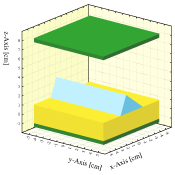
A ridge (blue) used to model a surface irregularity of a dielectric medium (yellow) between conductors (green).
Additional information on:
Format:
SPHERE  CENTRE cx cy cz ...
        RADIUS r ...
        [VOLTAGE v] ...
        [FLOATING-CONDUCTOR] ...
        [CHARGE q] ...
        [EPSILON eps] ...
        [material] ...
        [LABEL label] ...
        [N n]
        [DISCRETISATION discretisation] ...
Illustration:
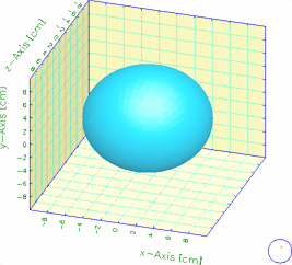
A sphere with 50 by 50 panels, shown with a colour table of 50 elements.
Additional information on:
These are to be used if the cell contains wires that are non-parallel or short compared to their length. If the cell can be described in terms rows of long and parallel wires, planes, a tube and periodicity, then it is preferable to do so.
Wire solids are treated as cylinders for most purposes, but neBEM handles them as charges distributed along the axis in such a manner that the surface is at the specified potential. This is equivalent to the thin-wire approximation used for wire and plane cells. This approach makes more efficient use of the elements than a solid cylinder in case the radius of the cylinder is small compared to its length and to the distance to other electrodes. A CYLINDER should be used if these conditions are not fulfilled.
Wires are always conductors.
Mandatory parameters are the location of the centre, the radius and the length. The direction defaults to the z-axis.
Format:
WIRE  CENTRE cx cy cz ...
      RADIUS r ...
      HALF-LENGTH lz ...
      [DIRECTION dx dy dz] ...
      [VOLTAGE v] ...
      [FLOATING-CONDUCTOR] ...
      [material] ...
      [LABEL label] ...
      [DISCRETISATION discretisation]
Example: Two perpendicular wires cross each other at a distance of 1\ mm.
&CELL
nebem target-element-size 0.01 maximum-elements 100
solids
wire centre      0      0   -0.05 ...
     half-length 1 ...
     radius      0.0100 ...
     direction   1      0    0 ...
     voltage    -1
wire centre      0      0   +0.05 ...
     half-length 1 ...
     radius      0.0100 ...
     direction   0      1    0 ...
     voltage    +1

&FIELD
area -0.25 -0.25 -0.25 0.25 0.25 0.25 view z=0
grid 50
plot-field surface e

area -1.2 -1.2 -1.2 1.2 1.2 1.2 view z=0
plot-field surface e

track -1 0.010001 -0.05   1 0.010001 -0.05
plot-field graph v range -1.01 -0.99
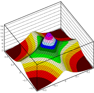
The first plot (reproduced below), like the second, shows how the field increases in the
area where the wires are nearest to each other. The third plot verifies the boundary condition.
Additional information on:
Formatted on 21/01/18 at 16:55.